
Robot control apparatus, robot control method, and program

Inactive Publication Date: 2019-09-26
NIDEC CORP
View PDF0 Cites 4 Cited by
  • Summary
  • Abstract
  • Description
  • Claims
  • Application Information

AI Technical Summary

Benefits of technology

The patent describes a robot control system that can move a reference point of a robot along a straight line between two points. The system uses a combination of linear interpolation and constant velocity segments to achieve smooth motion. The system can also adjust the angular velocities of each segment to improve the overall motion time of the robot. The technical effect of this system is improved efficiency and smooth movement of a robot along a straight line.

Problems solved by technology

However, since a movement path is not ensured in the PTP control, the distal end of the arm has the possibility of a collision with other objects or walls in a working space of the robot.
However, conventionally, the distal end of the arm of the robot cannot move at a high speed.

Method used


Image

  • Robot control apparatus, robot control method, and program
  • Robot control apparatus, robot control method, and program
  • Robot control apparatus, robot control method, and program

Examples


Embodiment Construction

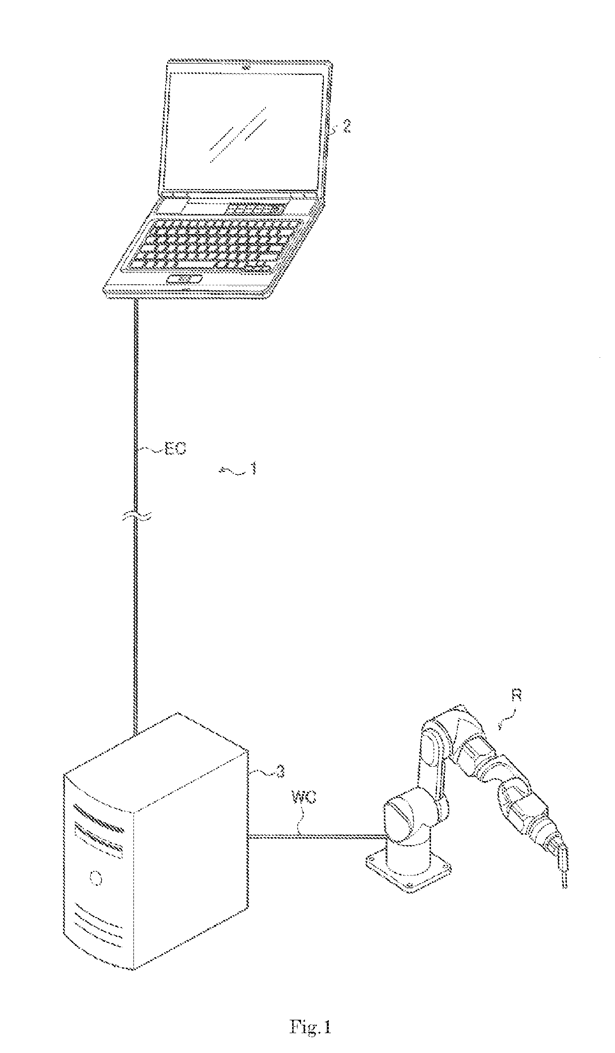
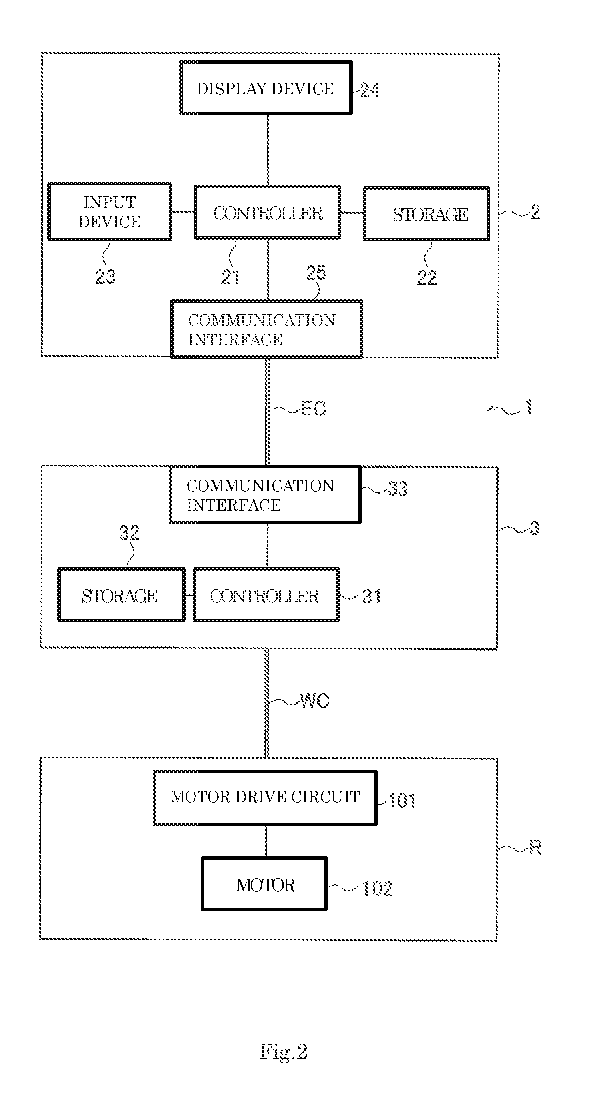
[0022]Hereinafter, robot systems each including a robot control apparatus according to example embodiments of the present disclosure will be described.

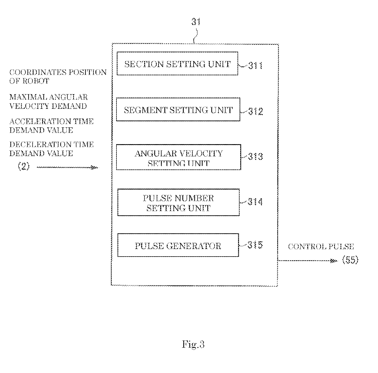
[0023]In the robot system according to each of the example embodiments, a distal end of an arm of a robot, i.e., a position which is an attachment reference of an end effector as a reference point of the robot, is controlled to be moved by linear interpolation control from a start point to an end point. In the linear interpolation control, a straight line connecting the start point to the end point is divided into a plurality of segments, and the robot is operated by point to point (PTP) control in each of the plurality of segments. In this case, a PTP operation in each of the segments optimally determines an angular velocity in each of the segments as a constant angular velocity, thereby implementing a high-speed pseudo-linear motion.

[0024]In the following description, the reference point of the robot means a position of the robot wh...


PUM


Abstract

A robot control apparatus includes a section setter to set, on a straight line connecting a start point to an end point, an acceleration section until reaching a predetermined angular velocity, a constant velocity section in which the predetermined angular velocity is maintained, and a deceleration section in which the predetermined angular velocity is decreased, a segment setter to divide each of the acceleration section, the constant velocity section, and the deceleration section into segments and to set segment distances of each of the acceleration section, the constant velocity section, and the deceleration section so as to equalize or substantially equalize moving times of the segments of the reference point to each other, and an angular velocity setter to set, when the reference point is moved in each of the segments according to point to point control, an angular velocity of each of the segments based on a variance in angle that becomes maximum with respect to each of the segments in each of the acceleration section, the constant velocity section, and the deceleration section.

Description

CROSS REFERENCE TO RELATED APPLICATION[0001]This application claims the benefit of priority to Japanese Patent Application No. 2018-058534 filed on Mar. 26, 2018. The entire contents of this application are hereby incorporated herein by reference.1. FIELD OF THE DISCLOSURE[0002]The present disclosure relates to a robot control apparatus, a robot control method, and a program.2. BACKGROUND[0003]Conventionally, point to point (PTP) control is known as a path control method of moving a position of a distal end of an arm (an end of a hand) of a robot from a start point (teaching point) to an end point (teaching point). Further, linear interpolation control of moving the position of the distal end of the arm of the robot along a linear path is known.[0004]The conventional robot control apparatus includes a robot speed calculation device having a part for acquiring current position information on a robot, a part for acquiring maximal rated speed information on a joint of the robot, and a ...

Claims


Application Information

Patent Timeline
IPC IPC(8): B25J9/16B25J9/12
CPCB25J9/12B25J9/1664B25J9/1651B25J9/0081B25J17/02G05B2219/43033B25J9/1602B25J9/1692B25J9/1658
Inventor DOAN, THANH NHATYOSHIDATSUNETA, HARUHIRO
Owner NIDEC CORP
Learn More