Brain imaging system and method

a brain imaging and brain imaging technology, applied in the field of brain imaging system and brain imaging method, can solve problems such as adversely affecting precision and efficiency

Inactive Publication Date: 2019-10-03
A MOY LTD
View PDF0 Cites 3 Cited by
  • Summary
  • Abstract
  • Description
  • Claims
  • Application Information

AI Technical Summary

Problems solved by technology

However, the two-dimensional image can only be interpreted by medic...

Method used


Image

  • Brain imaging system and method
  • Brain imaging system and method
  • Brain imaging system and method

Examples


Embodiment Construction

[0014]The aforementioned illustrations and following detailed descriptions are exemplary for the purpose of further explaining the scope of the present disclosure. Other objectives and advantages related to the present disclosure will be illustrated in the subsequent descriptions and appended drawings. In these drawings, like references indicate similar elements.

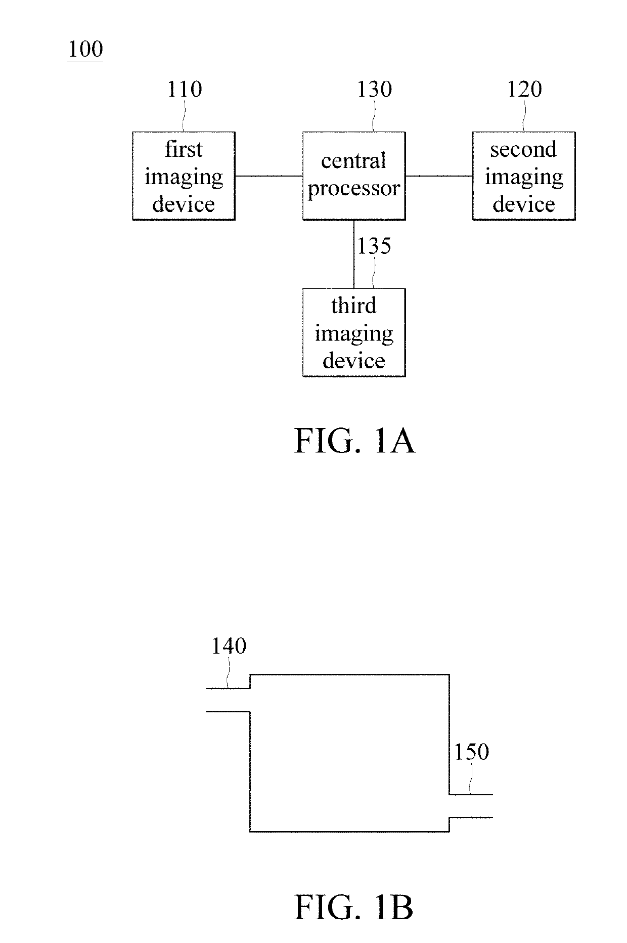
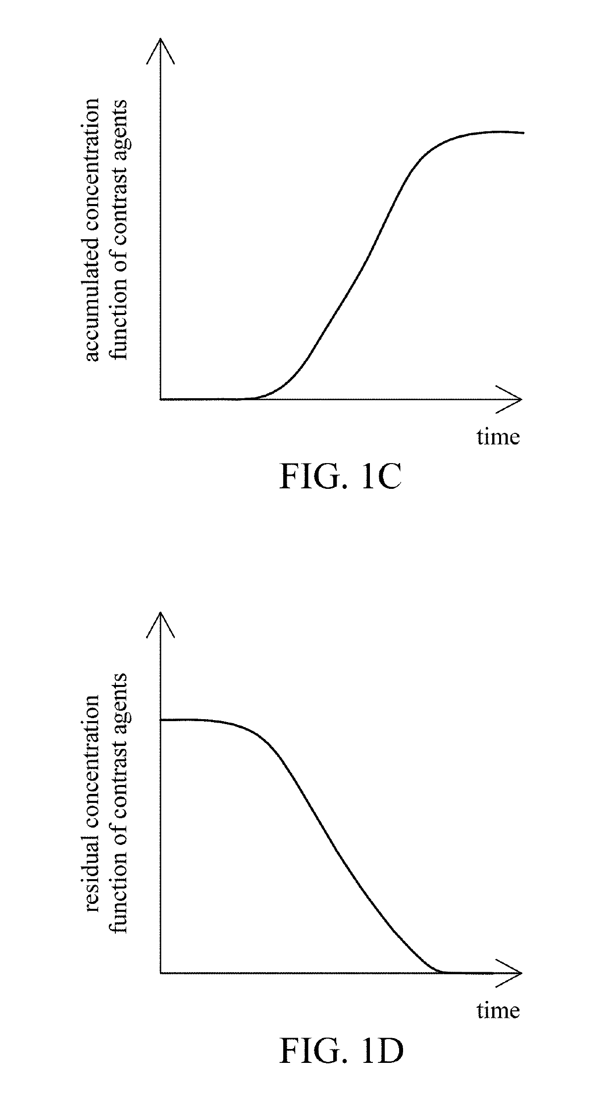
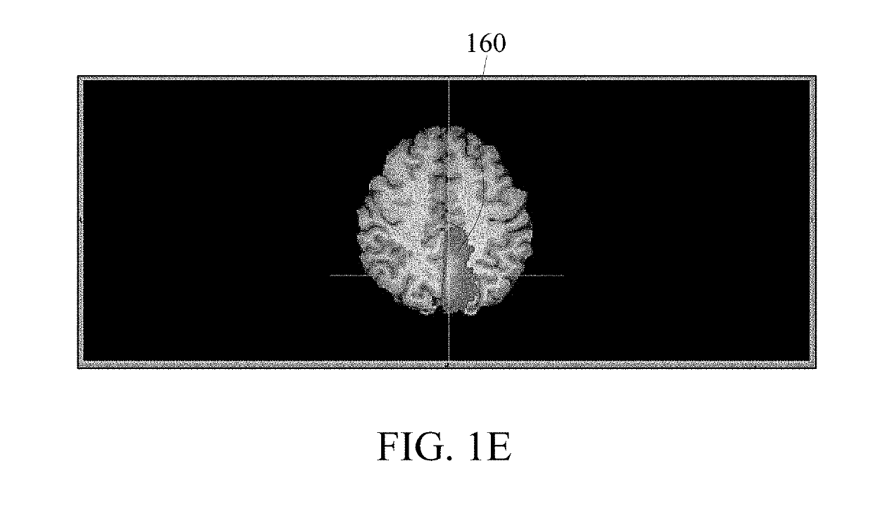
[0015]FIG. 1A shows a block diagram of a brain imaging system according to one embodiment of the present disclosure, FIG. 1B is a schematic diagram showing a flow path of contrast agents according to one embodiment of the present disclosure, FIG. 1C is a curve diagram showing an accumulated concentration function of a contrast agent according to one embodiment of the present disclosure, FIG. 1D is a curve diagram showing a residual concentration function of a contrast agent according to one embodiment of the present disclosure, and FIG. 1E shows a schematic diagram of a brain image according to one embodiment of the present ...


PUM


Abstract

A brain imaging system includes a first imaging device, a second imaging device, a third imaging device and a central processor. The first imaging device captures a first brain image, and calculates a cerebral blood flow, a cerebral blood volume, a cerebral blood mean transit time and a first contrast agent time to peak. The second imaging device captures a second brain image, and calculates the cerebral blood flow, the cerebral blood volume, the cerebral blood mean transit time and a second contrast agent time to peak. The central processor generates an image of a vessel occlusion, infarction or ischemia region respectively according to the vessel occlusion, infarction or ischemia regions in the first brain image and in the second brain image. The third imaging device obtains a brain atrophy region according to the cerebral cortex volume calculated by the third imaging device.

Description

CROSS-REFERENCE TO RELATED PATENT APPLICATION[0001]This application claims the benefit of priority to Taiwan Patent Application No. 107111316, filed on Mar. 30, 2018, now Taiwan Patent No. 1644653. The entire content of the above identified application is incorporated herein by reference.BACKGROUND OF THE INVENTION1. Field of the Invention[0002]The present disclosure relates to an imaging system and an imaging method; in particular, to a brain imaging system and a brain imaging method.2. Description of Related Art[0003]Nuclear magnetic resonance (NMR) is a non-invasive way to detect human bodies. It obtains variations of magnetic dipole moment of water molecules through transmitting and receiving radio frequency signals, and further to differentiate normal and tumor tissues by using contrast agents. The computerized tomography (CT) is used to obtain a two-dimensional image by having X-rays scanned through a human body. However, the two-dimensional image can only be interpreted by me...

Claims


Application Information

Patent Timeline
IPC IPC(8): A61B6/00A61B6/03A61B5/055G06K9/62G06V10/147
CPCA61B6/507A61B6/032A61B6/501A61B5/055A61B6/481A61B6/5247A61B6/504G06K9/6296A61B2576/026A61B5/0263G16H30/40G06V10/147G06V2201/03G06F18/29
Inventor YANG, FAN-PEI
Owner A MOY LTD
Why Eureka
Try Eureka