Tissue fusion instrument, in particular a tissue fusion forceps

Active Publication Date: 2019-10-03
ERBE ELEKTROMEDIZIN GMBH
View PDF0 Cites 0 Cited by
  • Summary
  • Abstract
  • Description
  • Claims
  • Application Information

AI Technical Summary

Benefits of technology

[0007]An object of the embodiments disclosed herein is to create a tissue fusion instrument that

Problems solved by technology

No connection, however, is provided between the electro

Method used


Image

  • Tissue fusion instrument, in particular a tissue fusion forceps
  • Tissue fusion instrument, in particular a tissue fusion forceps
  • Tissue fusion instrument, in particular a tissue fusion forceps

Examples


Embodiment Construction

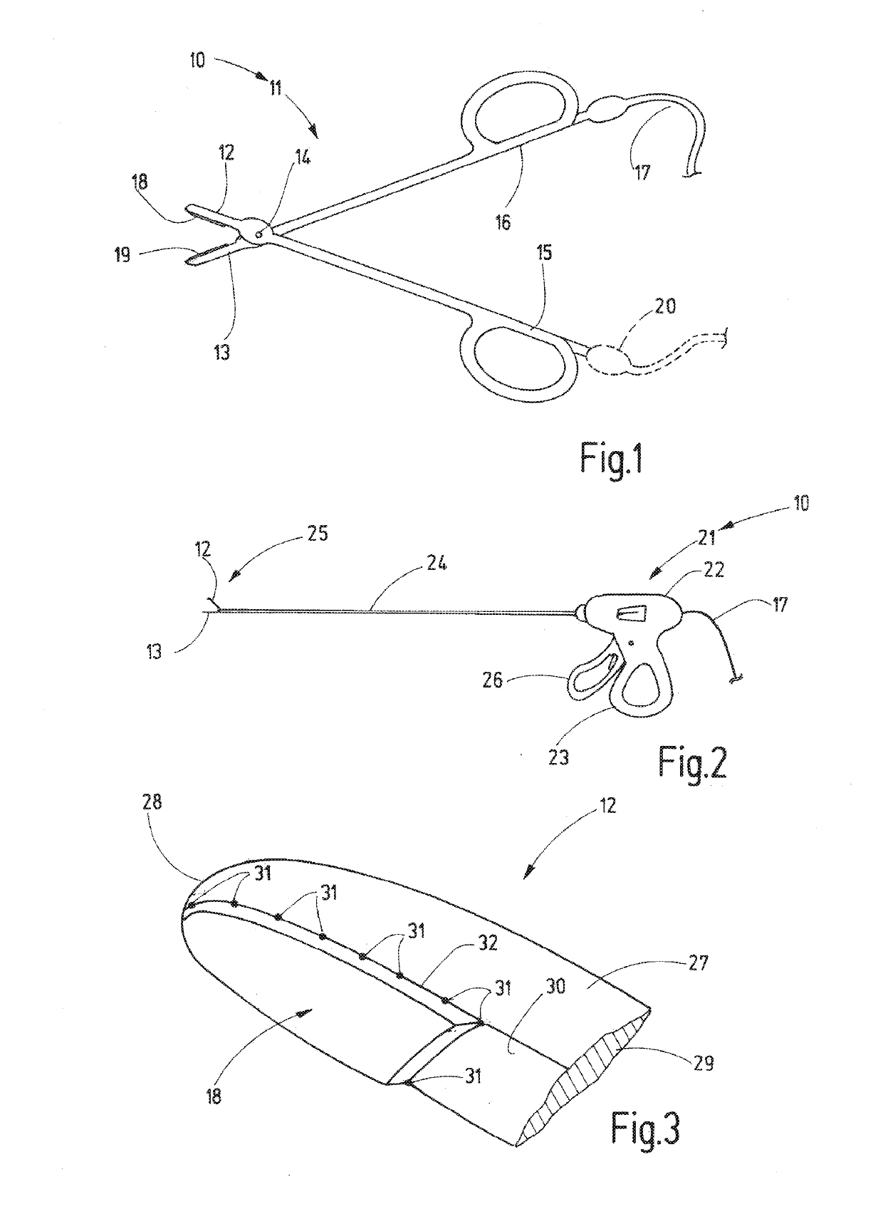
[0033]FIG. 1 shows an electrosurgical tissue fusion instrument 10 in the form of a tissue fusion forceps 11. The instrument 10 has a first arm 12 and a second arm 13, which are connected to each other by an articulated joint. In the illustrated embodiment, a hinged joint 14, for example, is used for the connection of the arms 12, 13. The arms 12, 13 are connected to handles 15, 16 by which the arms 12, 13 can be moved towards each other and away from each other. At least one of the handles 15, 16 is provided with an electrical supply line 17, through which electric current can be supplied to the electrodes 18, 19 on the arms 12, 13 for coagulation of a vessel gripped between said arms 12, 13. Alternatively to a design with a single (two-core) supply line 17 on the handle 16, each of the handles 15, 16 can be provided with a electrical supply line 17, 20 respectively (i.e., single-core).

[0034]As shown schematically in FIG. 2, the tissue fusion instrument 10 can also be designed as a ...


PUM


Abstract

A tissue fusion instrument having electrodes that are only connected in a punctiform manner to their electrode carrier such that they are electrically conducting and thus, heat-conducting. As a result, heat transfer from the electrode to the respective electrode carrier is restricted. This, on one hand, benefits the desired surgical outcome and, on the other hand, prevents parasitic heating of the surgical instrument and concomitant damage to surrounding tissue.

Description

RELATED APPLICATION[0001]This application claims priority to European patent application EP 11 176 186.2, filed on Aug. 1, 2011, which is hereby incorporated by reference in its entirety.TECHNICAL FIELD[0002]Embodiments disclosed herein relate to a tissue fusion instrument such as a tissue fusion forceps.BACKGROUND[0003]Tissue fusion instruments are used, for example, to clamp and seal blood vessels using current and the effects of heat. For example, vessel walls lying opposite one another are pressed against each other by two electrodes and heated by current flow such that they adhere to each other in the long term. Here, the effect of heat should be limited where possible to the tissue areas to be fused. The aim is to avoid adversely affecting or damaging surrounding tissue.[0004]The basic design of a tissue fusion instrument is shown in US patent application publication 2006 / 0264922 A1, for example. The instrument is designed in the form of forceps with two arms electrically insu...

Claims


Application Information

Patent Timeline
IPC IPC(8): A61B18/14
CPCA61B18/1445A61B2018/0063A61B2018/1412A61B2018/1455
Inventor FISCHER, KLAUSBRODBECK, ACHIMSCHAELLER, DANIEL
Owner ERBE ELEKTROMEDIZIN GMBH
Why Eureka
Try Eureka