Camera sight device for a weapon

a camera sight and weapon technology, applied in the field of weapon camera sight devices, can solve the problems of not being able to effectively pinpoint a target, putting the firearms user in harm's way to the accurate use of the weapon, and affecting the overall range of use so as to expand the range of adaptation of the camera sight, and enhance the overall range of use

Active Publication Date: 2019-10-03
CAMPBELL ROBERT MARSHALL
View PDF0 Cites 14 Cited by
  • Summary
  • Abstract
  • Description
  • Claims
  • Application Information

AI Technical Summary

Benefits of technology

[0010]According to an embodiment, an object of the instant embodiment is to provide a firearm sight system that includes a new type of camera sight, as well as several accessories, that have been designed to work as an integral part of or to work in conjunction with the instant camera sight in different forms and applications to expand and enhance overall range of use. The firearm sight is designed to be adapted to, or incorporated into, any type of reflex or holographic type firearm sight, but also the same camera sight can be incorporated, or adapted to, tactical prism sights, as well as scopes. The camera sight in one design includes a tiny HD camera with infrared viewing capabilities and its own Wi-Fi transmitting module. The camera is mounted in a position where the camera can receive an image from behind a front window or lends of the sight where the image of the target or surrounding area first enters the sight and the camera would be mounted in a particular vantage point where the image of the reticle provided by the sight can be viewed as true to the target. This camera would have infrared capabilities as well as its own Wi-Fi transmitting module with this Wi-Fi transmitting module being either part of this camera or this Wi-Fi transmitting module being a separate unit that is hard wired to the camera and mounted separately. The Wi-Fi transmitting module would transmit the image and sound received from the front window of the sight or lens of the sight to a smart device or any other device that can receive and display a transmitted Wi-Fi image such as a smart phone, computer, glasses, or goggles, computer watch such as an iWatch, or any computer or tablet. The screen on the smart device may be used in connection with the sight, the screen would become the sight screen for the sight and in turn the sight screen for the firearm that the camera sight is mounted to. The overall range of adaptation and application of tiny HD cameras with infrared viewing capabilities and Wi-Fi transmitters that are either attached to or incorporated into a design of these various types of tactical sights and scopes. The small size of the HD cameras expand camera sights range of adaptation and application, particularly when incorporated into the design of a parallax free type reflex sight, including red dot type sights, or parallax free holographic type sights. The advantage of a parallax free is that a parallax free sight keeps the image of the reticle provided by the sight as well as the image of the target and surrounding area true to matter the angle the user would be viewing the image displayed by the sight's window. For this reason, the camera incorporated into a parallax free type sight can be mounted anywhere about the firearm as long as the camera can acquire a clear view of the sight's window where the image of target and surrounding area, as well as the image of the reticle, tha is provided by the sight and their placement to each other, remain the same whether the user is viewing the image in the sight while using the sight in a regular or conventional manner or whether the user is viewing the image of the target behind the reticle and surrounding area that is transmitted by Wi-Fi from the camera sight to a smart phone or any other device that can receive and display a Wi-Fi signal. These two images would remain identical with the reticle remaining true to the target, both in the sight so the user can view the target in either manner or both at the same time and with target always being viewable in the perfect center of the smart phone screen behind the reticle.
[0011]According to an embodiment, an object of the instant embodiment is to provide several accessories designed to enhance the camera sight's overall range of use that will be fully explained and better understood in the description and illustrations that follow as well as several other optional designs and applications of the camera sight described and illustrated in this application to better illustrate the versatility and range of use of the camera sight which can will be fully understood in the description and illustrations that follow.

Problems solved by technology

However, the prior art fails to allow a user to effectively pinpoint a target from off to the side or from any other position that could be in relation to the weapon.
Presently, a firearms user must be directly behind the weapon to sight a target, which exposes the firearms user in harm's way to the accurate use of the weapon.
In other words, in order to accurately locate, pinpoint, and fire on a target, the user of the firearm must become a target thereby presenting a problem in that first responders, soldiers, and law enforcement personnel often encounter hostile combatants, violent actors, or offenders who carry pistols, rifles, or other weapons.
The problem is that with friendly combatants' entire body being behind cover, a clear lineal view to be able to locate and accurately fire on advancing hostile forces cannot be accomplished without looking over or around these fortified structures to both locate and fire on hostiles, exposing himself as a target while doing so.

Method used


Image

  • Camera sight device for a weapon
  • Camera sight device for a weapon
  • Camera sight device for a weapon

Examples


Embodiment Construction

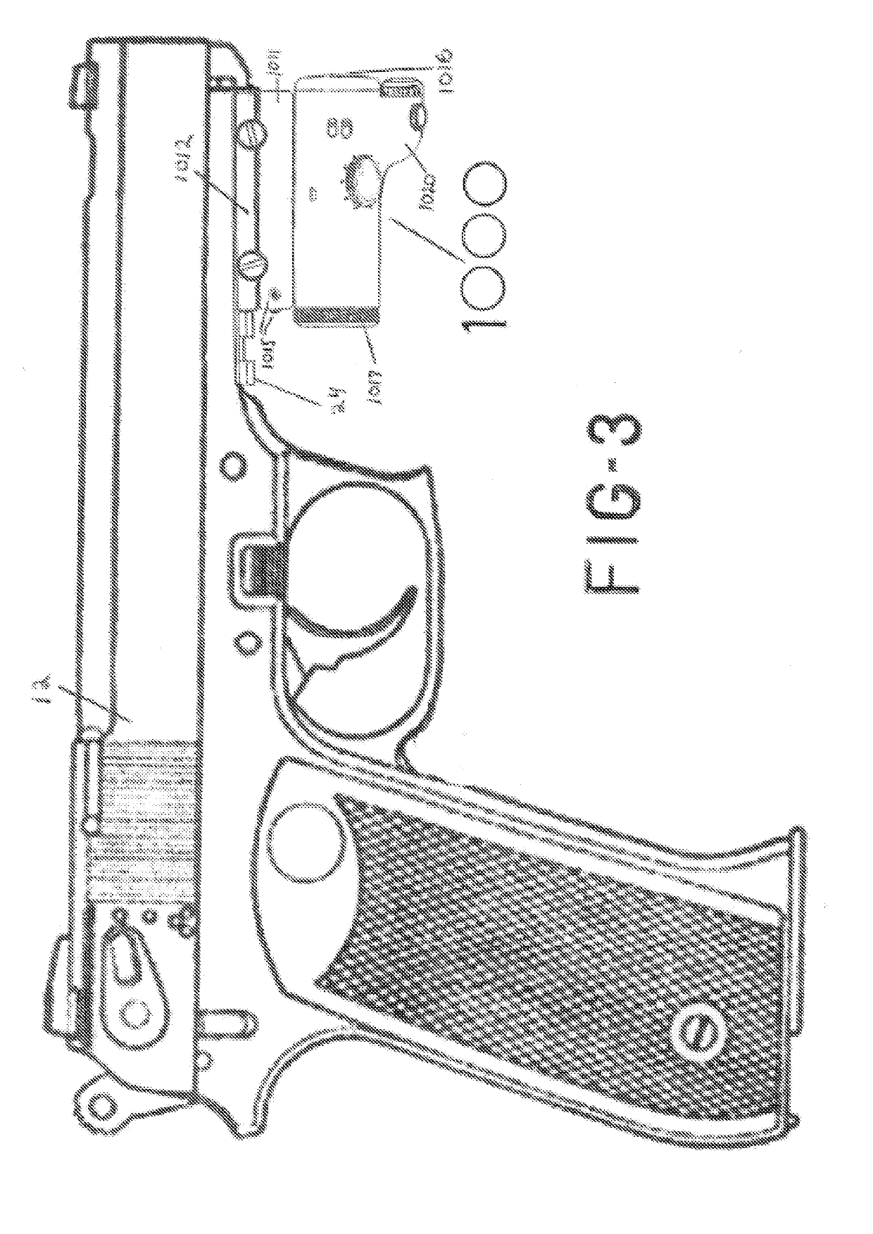
[0069]The present invention advantageously provides a sighting device for attachment to a weapon for providing a digital scope. The present invention contemplates various types of mounts and configurations of digitally displaying an accurate sight.

[0070]Accordingly, the components have been represented where appropriate by conventional symbols in the drawings, showing only those specific details that are pertinent to understanding the embodiments of the present invention so as not to obscure the disclosure with details that will be readily apparent to those of ordinary skill in the art having the benefit of the description herein.

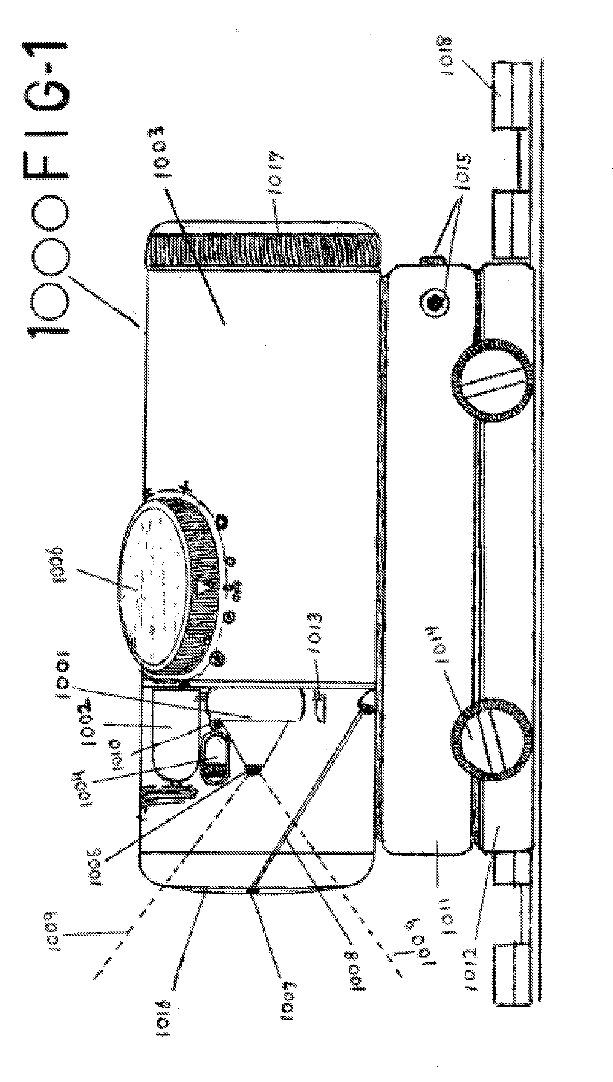
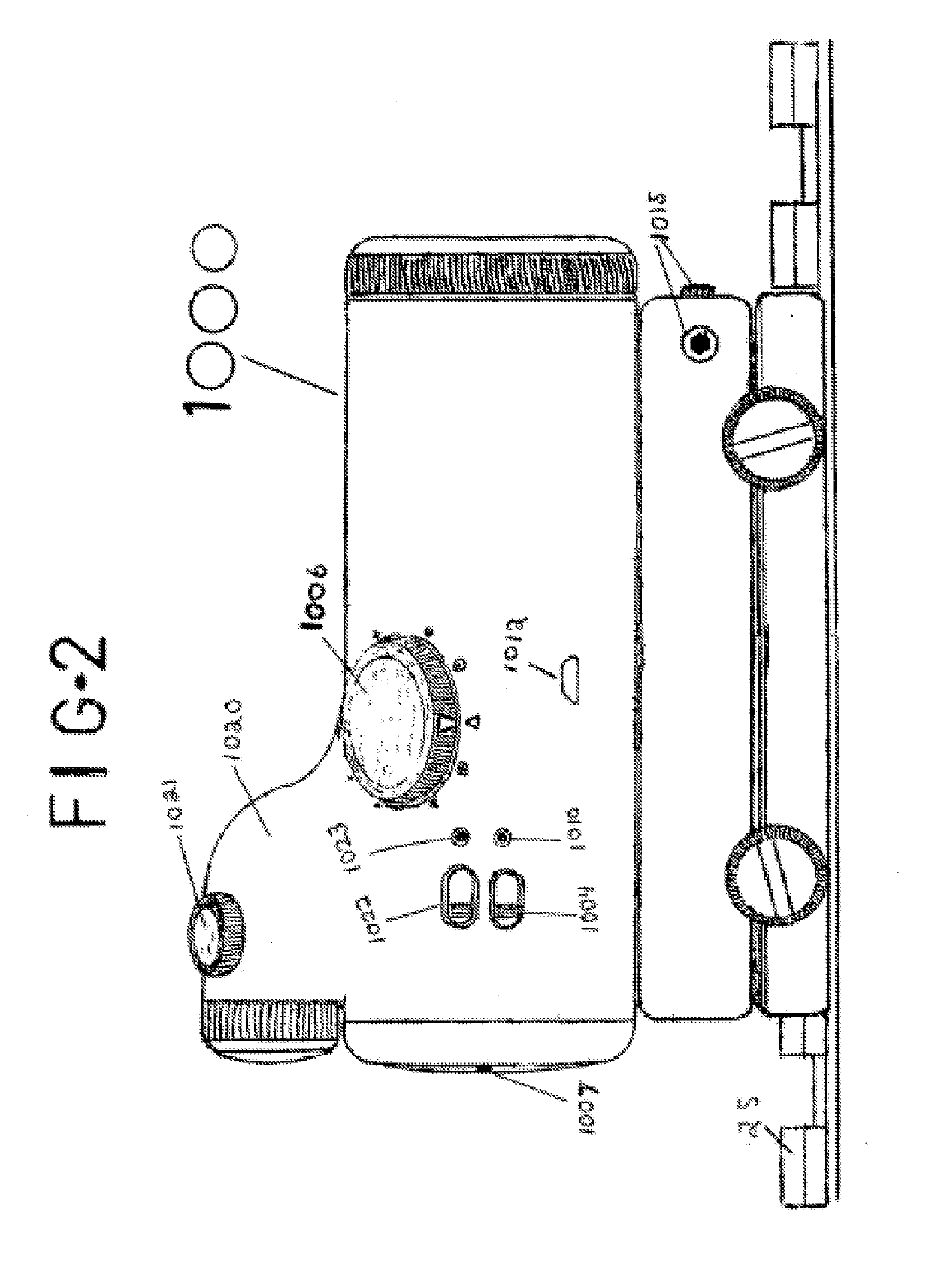
[0071]Referring now to the drawings figures in which like reference designators refer to like elements. FIG. 1 shows an exemplary camera sight constructed in accordance with the principles of the present embodiment and designated generally as camera sight 1000. A HD infrared viewing camera 1001 is hard mounted in a sight housing 1003 in a position such that...


PUM


Abstract

A camera system having a sight device, with a housing configurable for securing about a weapon, the camera connects with a smart phone device for displaying an image from the sight device for accurately targeting with a weapon.

Description

CROSS-REFERENCE TO RELATED APPLICATION[0001]This application is related to and claims benefit to U.S. Provisional Patent Application Ser. No. 62 / 386,055, filed Nov. 16, 2015, entitled DEVICE THAT IS MOUNTED ON RAIL SYSTEMS OF FIREARMS CONSISTING OF A MINIATURE CAMERA THAT TRANSMITS ITS OWN WIFI SIGNAL AND IS MOUNTED IN A HOUSING THAT IS INTEGRAL TO A SIGHT ADJUSTABLE RAIL MOUNT AND IS USED TO VIEW TARGETS FROM AROUND CORNERS OR FROM BEHIND EMBANKMENTS OR ANY OTHER BULLET PROOF POSITION WITHOUT EXPOSING YOURSELF OR YOUR POSITION WHILE DOING SO WITH TARGET VIEWED IN CROSSHAIRS OR RED DOT ON SMART PHONE SCREEN, the entirety of which is incorporated herein by reference; this application is related to and claims benefit to U.S. Provisional Patent Application Ser. No. 62 / 386,054, filed Nov. 16, 2015, entitled DEVICE THAT IS PRIMARILY MOUNTED ON RAIL SYSTEMS OF FIREARMS CONSISTING OF A MINIATURE CAMERA THAT IS HOUSED IN ITS OWN HOUSING THAT IS INTEGRAL TO A SIGHT ADJUSTABLE RAIL MOUNT AND ...

Claims


Application Information

Patent Timeline
Patent Type & Authority Applications(United States)
IPC IPC(8): F41G1/30F41G11/00
CPCF41G11/003F41G1/30F41C27/00G03B29/00F41G1/345F41G1/36G03B2206/00F41G3/165H04N23/51H04N23/57F41J5/10F41G1/00H04N23/00
Inventor CAMPBELL, ROBERT MARSHALL
Owner CAMPBELL ROBERT MARSHALL
Why Eureka
Try Eureka