Supercharge Your Innovation With Domain-Expert AI Agents!

Selective plane illumination microscopy with multiple illumination units scanning an object in sync with a digital camera rolling shutter

Active Publication Date: 2019-10-03
LYUBOSHENKO IGOR
View PDF0 Cites 2 Cited by
  • Summary
  • Abstract
  • Description
  • Claims
  • Application Information

AI Technical Summary

Benefits of technology

The patent text describes an illumination system for a microscope that produces a thin light sheet for selective plane illumination microscopy (SPIM) to improve image quality and reduce photo bleaching and photo toxicity. The system uses a laser light sheet with a stationary beam and a virtual light sheet created by rapidly scanning the object being imaged. The system also includes different embodiments of the illumination path and optical components of the illumination unit. The technical effect of the invention is to produce a thinner light sheet waist while maintaining image quality, allowing for faster imaging of medium-sized slices of opaque tissues and larger-sized clarified or translucent specimens.

Problems solved by technology

However, reducing the waist in this manner also leads to a quadratic decrease in the Rayleigh range.
This results in highly non-uniform, divergent light sheets that produce images with poor axial resolution and dramatic variations of the resolution throughout the field of view.
A marked loss of image quality results in a majority of applications requiring fast imaging of medium-sized slices of opaque tissues and / or in imaging of large-sized clarified or translucent specimens.

Method used


Image

  • Selective plane illumination microscopy with multiple illumination units scanning an object in sync with a digital camera rolling shutter
  • Selective plane illumination microscopy with multiple illumination units scanning an object in sync with a digital camera rolling shutter
  • Selective plane illumination microscopy with multiple illumination units scanning an object in sync with a digital camera rolling shutter

Examples


first embodiment

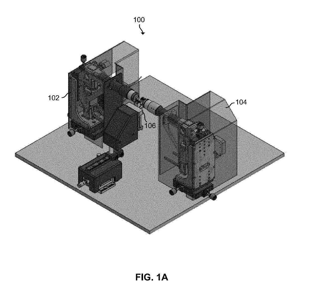
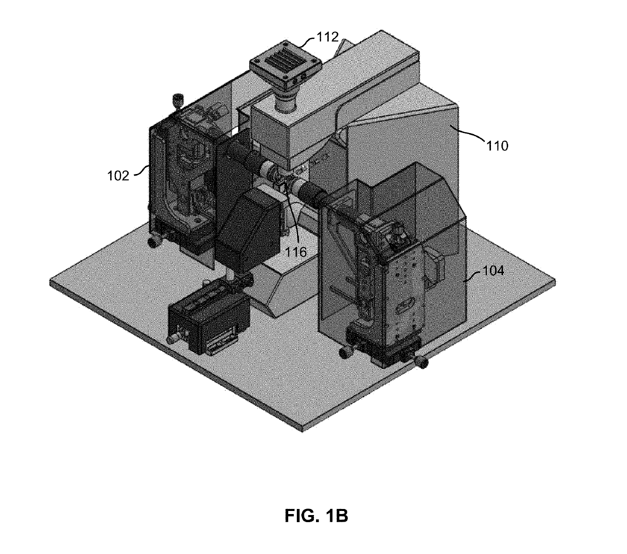
[0056]FIG. 3A-FIG. 3D are diagrams illustrating different views of an illumination path and optical components of an illumination unit. For example, the shown optical components are included and arranged in the shown relative order in illumination component 102 of FIGS. 1A-1B. In some embodiments, two illumination units are utilized and the shown optical components are included and arranged in the corresponding relative order (e.g., mirrored on z-plane from shown arrangement) in illumination component 104 of FIGS. 1A-1B. Not all components of the illumination have been shown. FIG. 3A shows a profile view. FIG. 3B shows a front view. FIG. 3C shows a top view. FIG. 3D shows a side view. The Z-direction axis is the vertical axis.

[0057]Illumination path 300 shows a path of light from light source 302 to a specimen in specimen chamber 318 as the light is manipulated by optical components to produce a light sheet to illuminate the specimen. An example of light source 302 is a laser light ...

second embodiment

[0064]FIG. 4A-FIG. 4D are diagrams illustrating different views of an illumination path and optical components of an illumination unit. For example, the shown optical components are included and arranged in the shown relative order in illumination component 102 of FIGS. 1A-1B. In some embodiments, two illumination units are utilized and the shown optical components are included and arranged in the corresponding relative order (e.g., mirrored on z-plane from shown arrangement) in illumination component 104 of FIGS. 1A-1B. Not all components of the illumination have been shown. FIG. 4A shows a profile view. FIG. 4B shows a front view. FIG. 4C shows a top view. FIG. 4D shows a side view. The z-direction axis is the vertical axis. A difference between illumination path 400 of FIG. 4A-FIG. 4D and illumination path 300 of FIG. 3A-FIG. 3D includes a location of variable focus lens component 310 in the illumination path relative to the other optical components. In illumination path 400, var...

third embodiment

[0065]FIG. 5A-FIG. 5D are diagrams illustrating different views of an illumination path and optical components of an illumination unit. For example, the shown optical components are included and arranged in the shown relative order in illumination component 102 of FIGS. 1A-1B. In some embodiments, two illumination units are utilized and the shown optical components are included and arranged in the corresponding relative order (e.g., mirrored on z-plane from shown arrangement) in illumination component 104 of FIGS. 1A-1B. Not all components of the illumination have been shown. FIG. 5A shows a profile view. FIG. 5B shows a front view. FIG. 5C shows a top view. FIG. 5D shows a side view. The z-direction axis is the vertical axis. A difference between illumination path 500 of FIG. 5A-FIG. 5D and illumination path 300 of FIG. 3A-FIG. 3D includes a location of variable focus lens component 310 in the illumination path relative to the other optical components. In illumination path 500, var...


PUM


Abstract

A system for illuminating a microscopy specimen includes illumination sources each of which is configured to emit a light that travels along an illumination path to illuminate the microscopy specimen placed on an optical detection path of an optical microscope. The system also includes optical elements in the illumination path of each of the illumination sources. The optical elements are configured to at least in part transform the light from each of the illumination sources into a light sheet illuminating the microscopy specimen and to vary a position of a waist of the light sheet from each of the illumination sources that illuminates the microscopy specimen. The optical elements for each of the illumination sources are configured such that the waist of the light sheet from each of the illumination sources are spatially aligned and illuminate a substantially coincident portion of the microscopy specimen.

Description

CROSS REFERENCE TO OTHER APPLICATIONS[0001]This application is a continuation in part of co-pending U.S. patent application Ser. No. 15 / 944,485 entitled VARYING AN ILLUMINATION PATH OF A SELECTIVE PLANE ILLUMINATION MICROSCOPY filed Apr. 3, 2018, which is a continuation in part of co-pending U.S. patent application Ser. No. 15 / 680,075, entitled EXTENDING OPTICAL MICROSCOPES TO PROVIDE SELECTIVE PLANE ILLUMINATION MICROSCOPY, filed Aug. 17, 2017, which claims priority to U.S. Provisional Patent Application No. 62 / 489,168, entitled EXTENDING OPTICAL MICROSCOPES TO PROVIDE SELECTIVE PLANE ILLUMINATION MICROSCOPY, filed Apr. 24, 2017, all of which are incorporated herein by reference for all purposes.[0002]This application claims priority to U.S. Provisional Patent Application No. 62 / 655,610 entitled SELECTIVE PLANE ILLUMINATION MICROSCOPY USING ILLUMINATION UNITS SCANNING AN OBJECT IN SYNC WITH A DIGITAL CAMERA ROLLING SHUTTER filed Apr. 10, 2018. This application claims priority to U....

Claims


Application Information

Patent Timeline
IPC IPC(8): G02B21/08G02B21/36G02B21/02G02B21/24G02B21/16H04N5/235H04N5/232
CPCH04N5/2353G02B21/241G02B21/08G02B21/025G02B21/16G02B21/36H04N5/2352H04N5/232127H04N5/2354G02B21/0032G02B21/0076G02B21/367G02B21/10H04N23/72H04N23/73H04N23/74H04N23/675
Inventor LYUBOSHENKO, IGOR
Owner LYUBOSHENKO IGOR
Features
  • R&D
  • Intellectual Property
  • Life Sciences
  • Materials
  • Tech Scout
  • Unparalleled Data Quality
  • Higher Quality Content
  • 60% Fewer Hallucinations
Learn More