Spatial light modulator apparatus

a technology of modulator and light source, which is applied in the field of spatial light source modulator apparatus and system, can solve the problems of reducing the performance reducing the efficiency of the user's existing microscope, and reducing the cost of specially designed microscopes, so as to achieve less complex, improve the performance, and reduce the cost

Inactive Publication Date: 2005-04-26
ANDOR TECH PLC
View PDF25 Cites 46 Cited by
  • Summary
  • Abstract
  • Description
  • Claims
  • Application Information

AI Technical Summary

Benefits of technology

[0011]It is therefore an object of this invention to provide a spatial light modulator apparatus which is less complex than a complete video projector unit with the necessary modification and additions, which is lower in cost, and which performs better.
[0012]It is a further object of this invention to provide such an apparatus which is useful with and easily coupled to existing microscopes.
[0014]It is a further object of this invention to provide such an apparatus and system which can be easily tailored to the user's specific microscope.
[0017]It is a further object of this invention to provide such an apparatus which eliminates the flicker associated with video projectors.
[0018]The invention results from the realization that instead of designing specially configured microscopes or coupling a complete video projector to an existing microscope, a lower cost spatial light modulator which produces mask pattern images in real time is effected by the combination of a specially designed optical head itself incorporating a DMD and a DMD controller digitally controlled by a digital interface responsive to a computerized pattern generation subsystem to provide a digital drive signal to the DMD controller corresponding to pattern image data produced by the pattern generation subsystem.
[0019]Instead of a video projector responsive to an analog VGA signal output from a computer graphics card as set forth in the '197 patent, the present invention operates solely in the digital realm by the use of a DMD interface which, in essence, provides to the DMD controller a map of DMD mirror settings corresponding to the mask pattern desired by the user. In this way, the illumination lamp need not be integral with the modulator apparatus and instead a wide variety of light source inputs may be used. Moreover, the complexity and cost of the modulator apparatus is severely reduced, the DMD controller is now a simple buffer, the modulator apparatus can be mounted to either the reflected light port, the transmitted light port, or the camera port of the microscope, a laser light input can even be used, and real time imaging accomplished.

Problems solved by technology

Surprisingly, however, the art is currently limited a) to specially configured microscopes employing LCDs and DMDs, (see, for example, U.S. Pat. Nos. 5,923,036; 5,587,832; and 5,923,466 incorporated herein by this reference) or, alternatively, b) to a microscope coupled to a complete video projector—the video projector itself incorporating, inter alia, an LCD or DMD, a light source, and the associated driver.
The drawbacks to such configurations are many.
Specially designed microscopes are expensive and render obsolete the user's existing microscopes.
Video projector type illuminating devices coupled to an existing microscope, on the other hand, results in an unduly complex, bulky, and expensive design, and, moreover, results in flickers and restrictions on the range of wavelengths which can be used in the microscope due to, inter alia, both the video projector design and the video input signal which operates the video projector.
For example, the use of a commercially available video projector with a DMD controlled by a computer graphics card for illumination in a microscope (U.S. Pat. No. 6,243,197) has significant drawbacks.
This type of illumination inherently ‘flickers’ and, although acceptable for overhead projections, is not adequate for scientific microscopy.
The temporal switching inherent in the method of pulse-width modulation (PWM) used to vary intensity levels in a projector system, combined with the electrical noise of the computer graphic card interface, may result in unacceptable flicker in a microscope system.
Furthermore, the spectral nature of the light source and optical coatings used in video projectors would restrict microscope studies to a wavelength range narrower than usual.

Method used


Image

  • Spatial light modulator apparatus
  • Spatial light modulator apparatus
  • Spatial light modulator apparatus

Examples


Embodiment Construction

[0042]Aside from the preferred embodiment or embodiments disclosed below, this invention is capable of other embodiments and of being practiced or being carried out in various ways. Thus, it is to be understood that the invention is not limited in its application to the details of construction and the arrangements of components set forth in the following description or illustrated in the drawings.

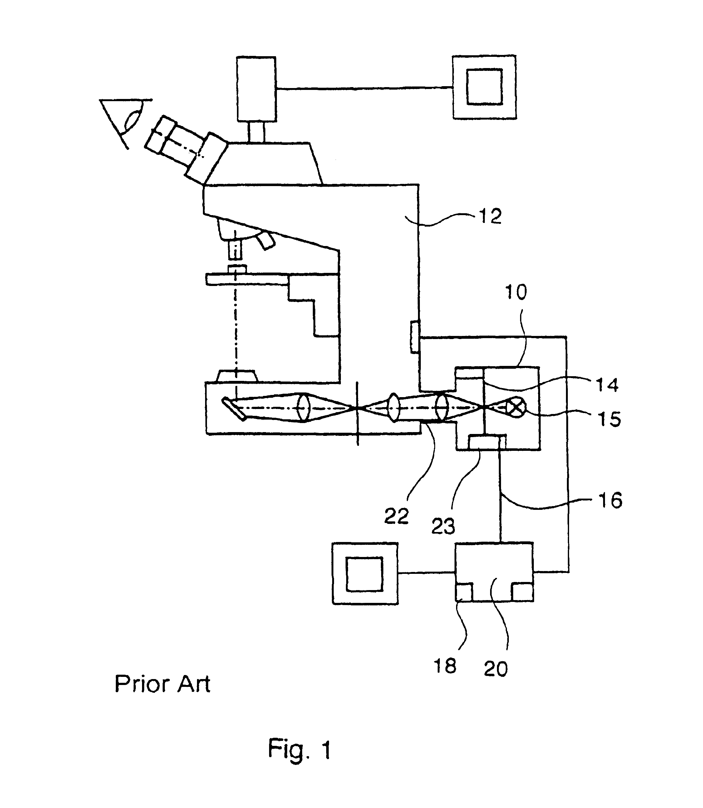
[0043]Prior art lighting device 10, FIG. 1 for microscope 12 is a complete video projector unit purporting to employ LCD or DMD 14, light source 15, and drive 23 connected via video cable 16 to graphic card 18 of “control / calculating device”20. Device 10 is connected to transmitted light port 22 of microscope 12 and graphics card 18 generates the image signal for driving LCD / DMD 14. The other components of this system are described in U.S. Pat. No. 6,243,197. The drawbacks, limitations, and problems associated with such a system are discussed in the background section above.
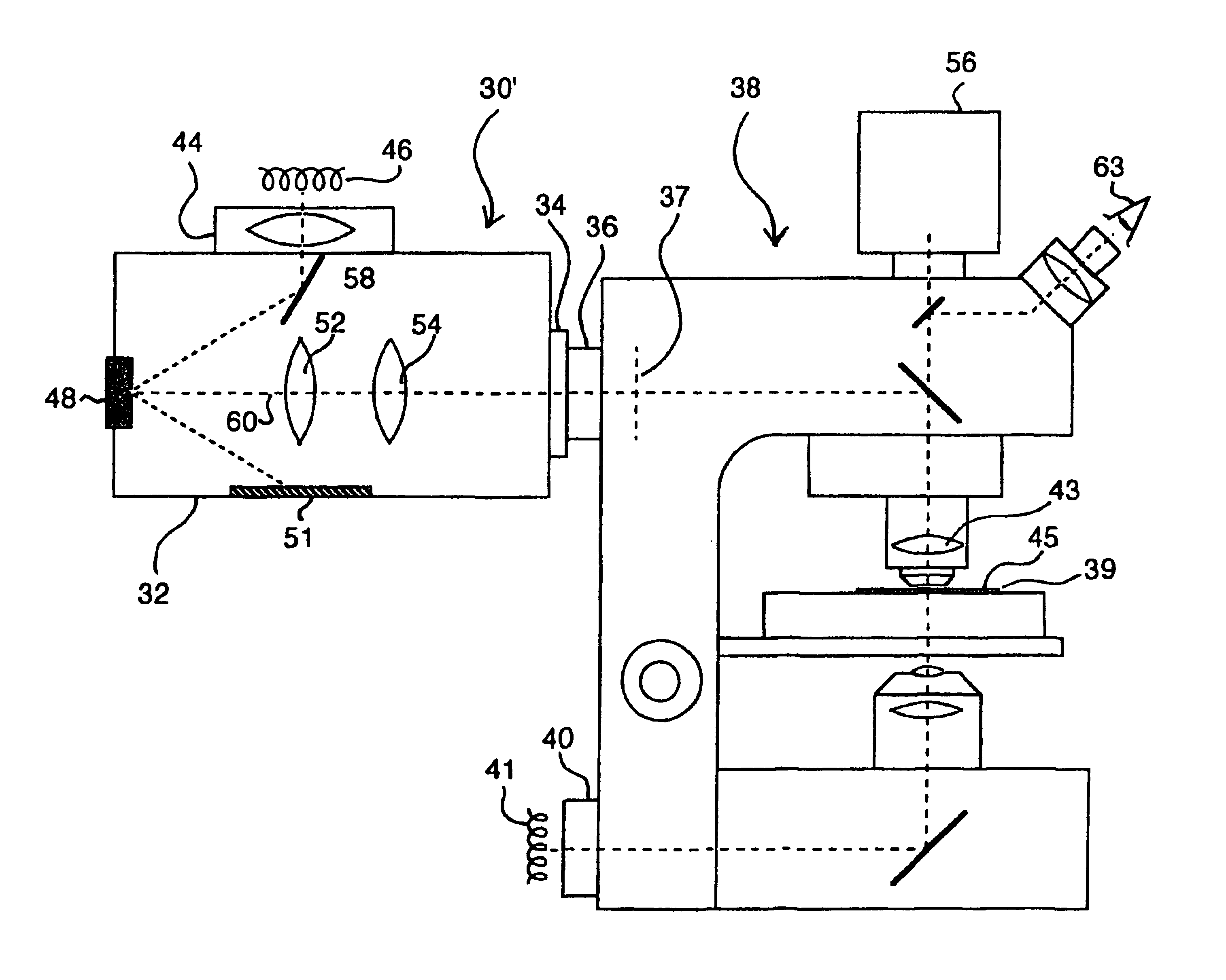
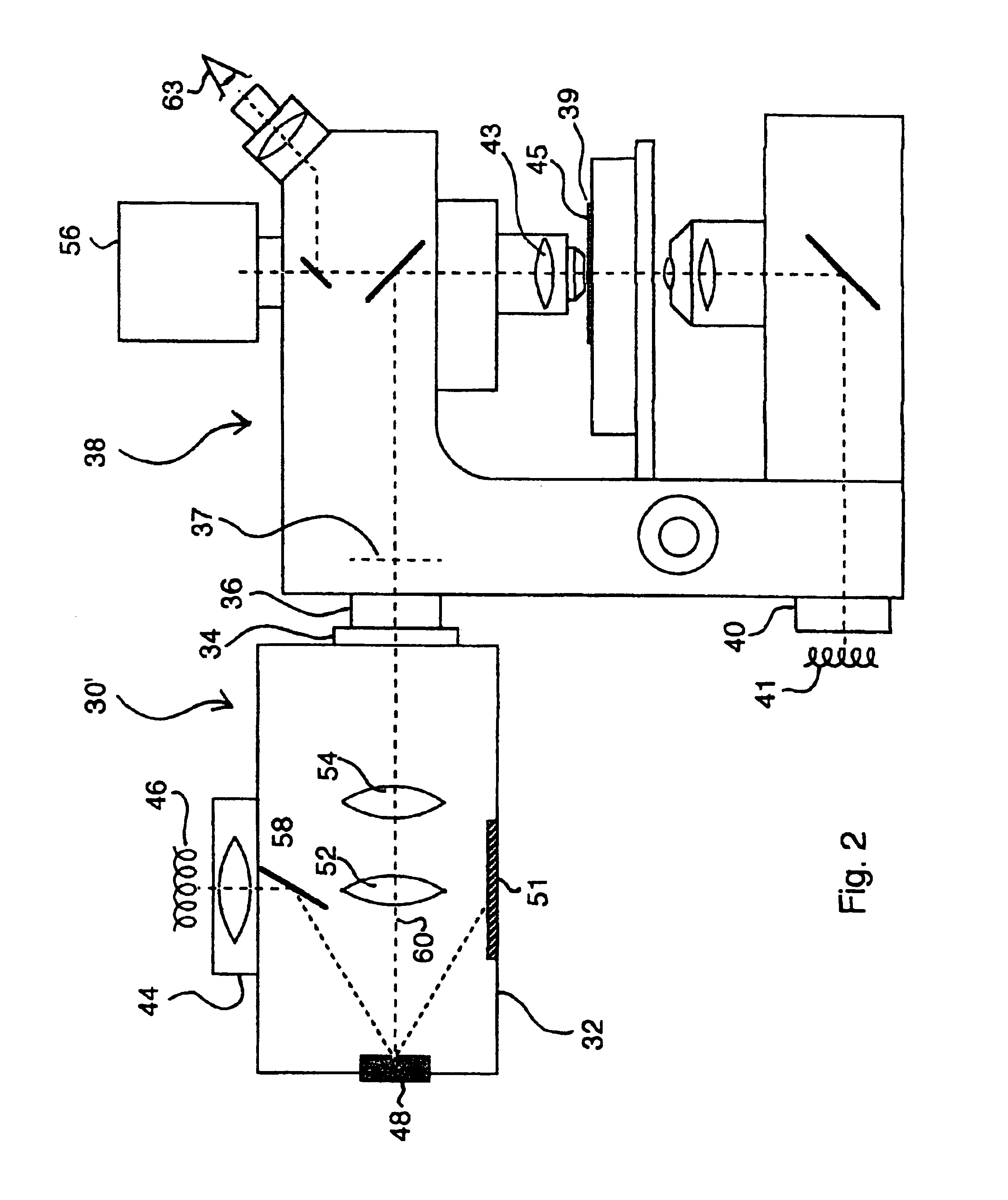
[0044]In this in...


PUM


Abstract

A spatial light modulator apparatus for an optical microscope system including an optical head with a mounting flange for mounting the optical head to a port of the microscope, a DMD for generating a pattern image of light, a light source mount for receiving a source of illumination, and one or more optical elements for directing light from the source of illumination to the DMD and to direct the pattern image generated by the DMD to the microscope. A DMD controller has a digital input and is connected to the DMD for driving the individual micromirrors of the DMD to generate the pattern image. A pattern generation subsystem is configured to output pattern image data and a digital interface is connected between the digital input of the DMD controller and the pattern generation subsystem, the digital interface configured to provide a digital drive signal to the DMD controller corresponding to the pattern image data.

Description

RELATED APPLICATIONS[0001]This application claims priority of U.S. provisional Ser. No. 60 / 337,801 filed Nov. 8, 2001 entitled AN ILLUMINATION SYSTEM FOR MICROSCOPES WHICH EMPLOYS A SPATIAL LIGHT MODULATOR DEVICE.FIELD OF THE INVENTION[0002]This invention relates to a spatial light modulator apparatus and system for use in conjunction with an optical microscope.BACKGROUND OF THE INVENTION[0003]Spatial light modulators such as liquid crystal displays (LCDs) and digital mirror devices (DMDs) (as available from Texas Instruments, for example) are used to modulate incident light into a spatial pattern to form a light image corresponding to an electrical or optical input. DMDs have been successfully incorporated into video projectors and printers, for example. See U.S. Pat. No. 5,535,047 incorporated herein by this reference.[0004]In the field of microscopes, it is often desirable to create a mask pattern to vary the illumination or viewing properties of the microscope using techniques s...

Claims


Application Information

Patent Timeline
Patent Type & Authority Patents(United States)
IPC IPC(8): G02B21/08G02B21/06G02B6/35G02B21/36G02B26/00
CPCG02B21/06G02B21/365G09G3/346G02B21/088G01N21/6458G09G2300/0857
Inventor DESIMONE, ANDREW FRANKCRARY, BRUCE
Owner ANDOR TECH PLC
Why Eureka
Try Eureka