Contact-field optical microscope

a contact-field optical microscope and microscope technology, applied in the field of fiber optics, can solve the problems of limiting the resolution of diffraction effects, unable to avoid the interference of the medium between the sample and the image detector, and difficulty in monitoring the dynamic variation of the microscopic state of energy in the nanometer range of samples

Inactive Publication Date: 2006-02-28
YU BI
View PDF15 Cites 45 Cited by
  • Summary
  • Abstract
  • Description
  • Claims
  • Application Information

AI Technical Summary

Benefits of technology

[0090]The core cross sectional diameter of each optical fiber at the sampling face is in the range of nanometer, thereby providing nanometer resolution of the sample image.

Problems solved by technology

Because of the interference of medium between sample and detector, it is difficult to monitor the dynamic variation of microscopic state of energy in nanometer range of sample by means of far-field and near-field optics.
Unlike traditional microscopes, scanning probe microscopes are near-field microscopes such as scanning tunneling microscopy, atomic force microscopy and near-field scanning optical microscopy, the techniques to overcome the diffraction limit, do not use lenses, so the size of the probe rather than diffraction effects generally limit their resolution.
Both of these two kinds of microscopes can not decrease the working distance to zero and therefore can not avoid the interference of the medium between the sample and the image detector.
This latter portion of the light or so called fiber-to-fiber cross-talk results in image quality degradation.
Loss in contrast transfer through the taper is primarily due to the percentage of non-image-forming light transmitted by the cladding of the taper.
This large amount of non-imaging (scattered) light limits the ratio of contrast transferred through the taper.
For a high magnifying fiber optical taper, the methods mentioned above is not simple enough and effective enough to confine the image light in optical fiber core and to block all of non-image forming light in the cladding totally.
The measurement of infrared radiation is complicated by the fact that water and bodily fluids are opaque to infrared light.
Consequently, even the slightest amount of water, bodily fluids, moisture, CO2 and many other medium on the collection end of a probe impairs the collection of infrared light.
As a result, conventional far-field and near-field optics is not good enough to be used in infrared procedures where moisture or bodily fluids are present.
Of course, application of this latter methodology to biological imaging is subject to the problem of high absorption of infrared radiation by water”.
However, conventional scanning probe microscopes generate images of sample areas slowly due to the sequential imaging of small, discrete points of sample areas required by the raster scanning technique.
Unlike electron image, the magnification of optical taper image is limited and difficult to adjust.
Although electron microscopes offer very fine resolution, the specimen must be prepared by high-vacuum dehydration and is subjected to intense heat by the electron beam, making observation of living specimens impossible.
The dehydration process also alters the specimen, leaving artifacts and sample damage that were not present in nature.
The fiber optic scintillating plates described above can work as contact-field model, but can not act as a sample image magnifier and require the coating with a reflective material, such as aluminum on the input side of the plate to re-directing the portion of the light which propagates back toward the input face.

Method used


Image

  • Contact-field optical microscope
  • Contact-field optical microscope
  • Contact-field optical microscope

Examples


Embodiment Construction

[0114]Three embodiments of the invention relating to visible light, infrared and UV, X-ray, charged particle contact-field optical microscopes have been described in detail with reference to the FIGS. 11A, 11B, 11C, 11D, 11E, 11F, 12A, 12B, 12C, 13A and 13B.

Visible Light Contact-Field Optical Microscope (FIGS. 11A, 11B, 11C, 11D, 11E, 11F)

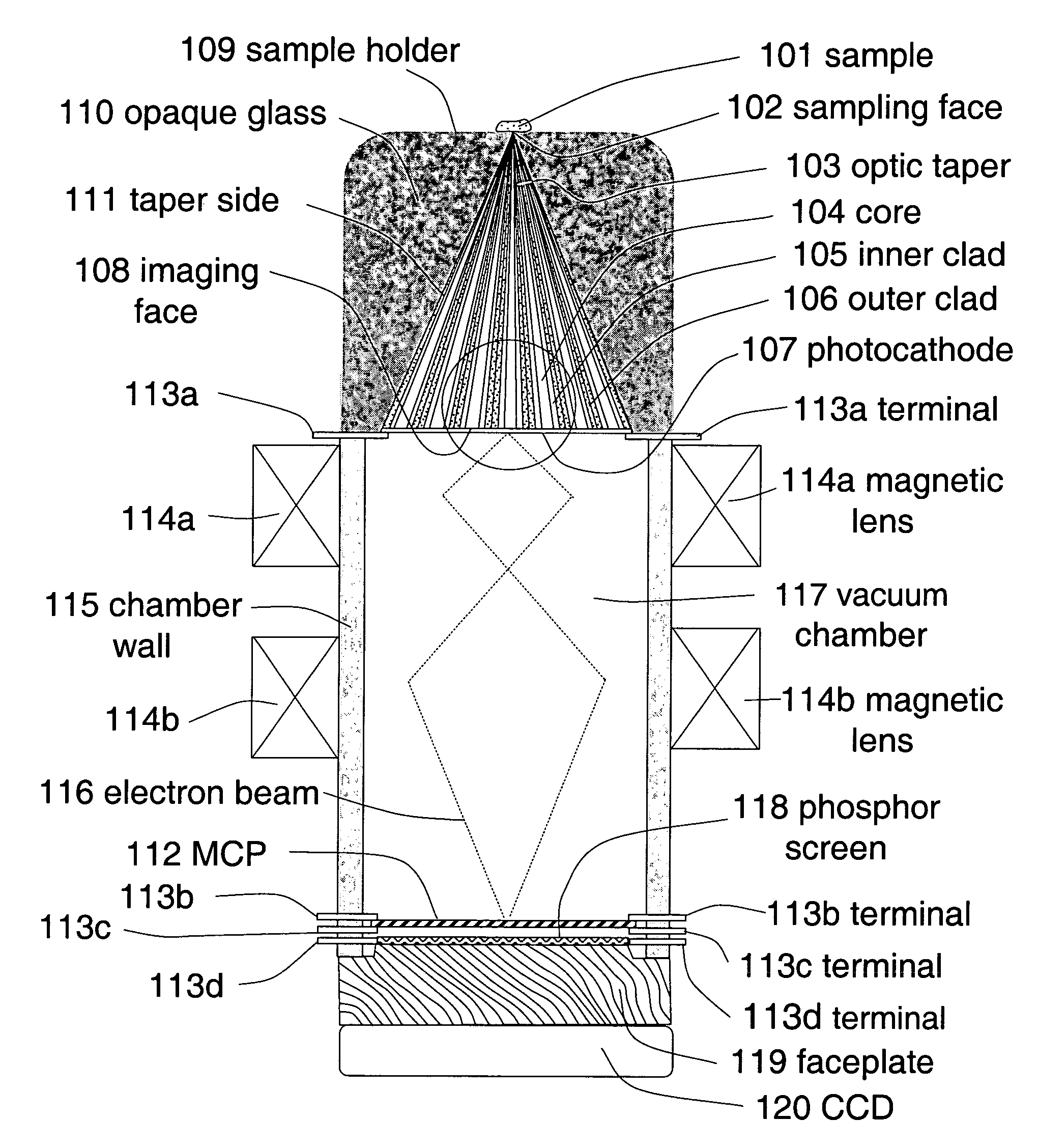
[0115]FIG. 11A is a schematic diagram of main portions of a contact-field optical microscope working at the range of visible light.

[0116]In this embodiment, the microscope comprises a fiber optical taper 103, a photocathode 107, a vacuum chamber 117, magnetic lenses 114a and 114b, a micro-channel plate (MCP) image intensifier 112, an image display phosphor screen 118, a high voltage power supply for MCP image intensifier, an electronic control circuit for magnetic lenses, a faceplate 119 and a CCD 120. The side 111 of the optical taper 103 is embedded in a light and radiation absorbing dark colored opaque glass 110 to prevent background light and r...


PUM


Abstract

A broad-spectrum, high spatial and time resolution contact-field optical microscope comprises a fiber optical taper, a vacuum chamber, a photocathode, a magnetic lens photoelectron image enlarger, a micro-channel plate image intensifier, a phosphor screen and a CCD. Sample is placed directly in contact with a smaller sampling face of the optical taper. Light which is emitted, reflected or transmitted by the sample is launched into each of the fiber core ends on the sampling face and conveyed by the optical fibers to a larger imaging face of the optical taper, thereby presenting an enlarged image at the imaging face. The image is converted into a photoelectron image by photocathode which is deposited on the surface of the imaging face. The photoelectron image is further enlarged by magnetic lenses and intensified by micro-channel plate. The enlarged and enhanced electron image is displayed on phosphor screen and coupled through faceplate to CCD.

Description

BACKGROUND OF THE INVENTION[0001]Electromagnetic force plays a main role relating to the great majority of chemical, physical and biological phenomenon in a wide range of material realm from atom to macroscopical objects except the involvements in the domains of atomic nucleus, elementary particles and astrophysics. The physical and chemical properties of the materials are also basically decided by the electromagnetic force. The electromagnetic force is very mighty. In almost all of natural phenomena, electromagnetic force plays an important even decisive role. The basic force of atomic nucleus combining electron to constitute atom, atoms joining together to compose molecules, molecules combining each other to form macroscopic objects (liquid, solid et al), is the electromagnetic interaction.[0002]Electromagnetic force is carried by photons. Electromagnetic radiation, such as light, can be thought of as being composed of photons. Photons of different energies (wavelength) span the e...

Claims


Application Information

Patent Timeline
Patent Type & Authority Patents(United States)
IPC IPC(8): G02B6/04
CPCG02B6/06G02B6/4298G02B6/14
Inventor YU, BI
Owner YU BI
Why Eureka
Try Eureka