Temporal-spatial resolution radiant flux diagnosis system

A diagnostic system and time-space resolution technology, applied in the field of laser fusion research, can solve the problems that the radiation flow cannot be detected separately, the time resolution can only reach 100 picoseconds, and there is no way to diagnose the spatial change process of the radiation flow, etc., and achieve high time resolution , the effect of high spatial resolution measurements

Active Publication Date: 2017-03-22
LASER FUSION RES CENT CHINA ACAD OF ENG PHYSICS
View PDF10 Cites 24 Cited by
  • Summary
  • Abstract
  • Description
  • Claims
  • Application Information

AI Technical Summary

Problems solved by technology

[0003] Typically, the detection of radiation streams is performed using a soft X-ray multi-channel energy spectrometer (Dante) [E. L. Dewald, K. M. Campbell, R. E. Turner, et al. Rev. Sci. Instrum. 75, 3759 (2004).] Peace Response X-ray detector (F-XRD) [Zhichao Li, Xiaohua Jiang, Shenye Liu, et al.Rev.Sci.Instrum. 81, 073504 (2010).], but these systems have no spatial resolution and can only detect the radiation inside the black cavity The total amount of the flow, the radiation flow at different positions in the black cavity cannot be detected separately, and the time resolution can only reach 100 picoseconds at the highest
Later, the limited pore type F-XRD [Kuan Ren, Shenye Liu, Huabing Du, et al. Rev. Sci. Instrum. 86, 103112 (2015).] was developed. This diagnostic system uses the method of adding limited pores to observe a certain Radiation flow in a fixed area, there is still no way to diagnose the spatial variation process of radiation flow
In addition, because it still uses F-XRD as the signal recording device, the time resolution is still only up to hundreds of picoseconds

Method used


Image

  • Temporal-spatial resolution radiant flux diagnosis system

Examples


Embodiment 1

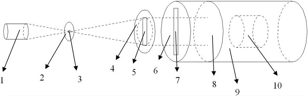
[0017] Such as figure 1 As shown, the spatiotemporal resolution radiation flow diagnostic system of the present invention includes a pinhole plate 2, an imaging plate 4 and a streak camera 9 arranged in sequence along the horizontal direction;

[0018] The center of the pinhole plate 2 has a pinhole 3;

[0019] There are vertical slits I5 on the imaging plate 4;

[0020] The front part of the streak camera 9 is a time resolution plate 6, the middle part is an X-ray photocathode 8, and the rear part is a streak camera focusing deflection system 10, and the time resolution plate 6 is provided with a slit II7 parallel to the slit I5; The X-ray photocathode 8 is a transmissive flat-response X-ray photocathode.

[0021] After the X-rays emitted by the black cavity 1 are imaged through the pinhole 3 on the pinhole plate 2, part of the X-rays are imaged on the imaging plate 4, and the other part of the X-rays passes through the slit I5 on the imaging plate 4 and then passes through...

Embodiment 2

[0025] The structure of this embodiment is the same as that of Embodiment 1, except that the horizontal distance L1=1cm between the imaging plate 4 and the time resolution plate 6, the pinhole plate 2 is a tantalum sheet with a thickness of 25 μm, The diameter of the pinhole 3 is 20 μm; the time resolution of the streak camera 9 is 20 ps, ​​and the spatial resolution is 50 μm.

Embodiment 3

[0027] The structure of this embodiment is the same as that of Embodiment 1, except that the horizontal distance L1=1cm between the imaging plate 4 and the time resolution plate 6, the pinhole plate 2 is a tantalum sheet with a thickness of 30 μm, The diameter of the pinhole 3 is 30 μm; the time resolution of the streak camera 9 is 30 ps, ​​and the spatial resolution is 100 μm.


PUM


Abstract

The invention provides a temporal-spatial resolution radiant flux diagnosis system, which is used for conducting precise diagnosis on the temporal and spatial evolution process of an X-ray radiant flux in a hohlraum. The hohlraum emits X-rays which undergo imaging by means of a pinhole in a pinhole plate, a portion of the X-rays is imaged onto an imaging plate; the other portion of the X-ray passes through a slit I in the imaging plate and then passes through a slit II in a time resolution plate to irradiate on an X-ray photocathode, further passes through a streak camera focusing deflection system and is recorded in a streak camera. According to the recorded signal, the temporal and spatial evolution process of the X-ray radiant flux emitted at a specified position of the hohlraum can be obtained. The temporal-spatial resolution radiant flux diagnosis system has time resolution with picosecond magnitude and temporal resolution with dozens of micrometer magnitude, and has wide application prospect.

Description

technical field [0001] The invention belongs to the field of laser fusion research and the field of X-ray detection, in particular to a time-space resolution radiation flow diagnosis system. Background technique [0002] In laser fusion research, the detection of black cavity radiation flow is very important research content. Through the diagnosis of the radiation flow, important information such as the coupling efficiency between the laser cavity target, the plasma density, and the temperature can be obtained. However, with the development of laser fusion research, further high-precision diagnosis of the spatiotemporal evolution of the radiation flow in the spot area, non-spot area, and target capsule in the black cavity is required. This is very important for the further understanding of the interaction between the laser cavity target, the verification of theoretical models and programs, and the final realization of fusion ignition. [0003] Typically, the detection of r...

Claims


Application Information

Patent Timeline
Patent Type & Authority Applications(China)
IPC IPC(8): G01T1/29
CPCG01T1/2921
Inventor 李晋刘慎业张文海胡昕杨志文陈韬黎宇坤袁铮邓克立邓博王强强董建军曹柱荣
Owner LASER FUSION RES CENT CHINA ACAD OF ENG PHYSICS
Why Eureka
Try Eureka