Analysis system and method of microbubble behavior in ultrasonic field based on superhigh speed photograph technology

An ultra-high-speed, ultrasonic field technology, applied in the use of sound waves/ultrasonic waves/infrasonic waves for material analysis, material analysis, ultrasonic/sonic waves/infrasonic wave diagnosis, etc.

Inactive Publication Date: 2006-10-18
XI AN JIAOTONG UNIV
View PDF1 Cites 36 Cited by
  • Summary
  • Abstract
  • Description
  • Claims
  • Application Information

AI Technical Summary

Problems solved by technology

According to the applicant's research, there are currently no related articles or patents in China on the use

Method used


Image

  • Analysis system and method of microbubble behavior in ultrasonic field based on superhigh speed photograph technology
  • Analysis system and method of microbubble behavior in ultrasonic field based on superhigh speed photograph technology
  • Analysis system and method of microbubble behavior in ultrasonic field based on superhigh speed photograph technology

Examples


Embodiment 1

[0116] Embodiment 1: Observing the behavior of microbubble groups in the ultrasonic field with an ultra-high-speed photography system

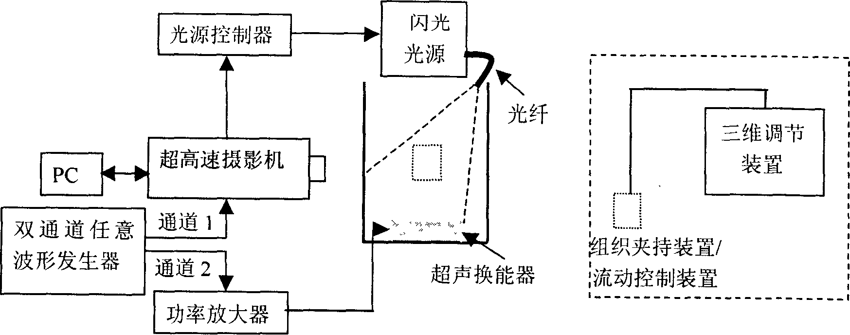
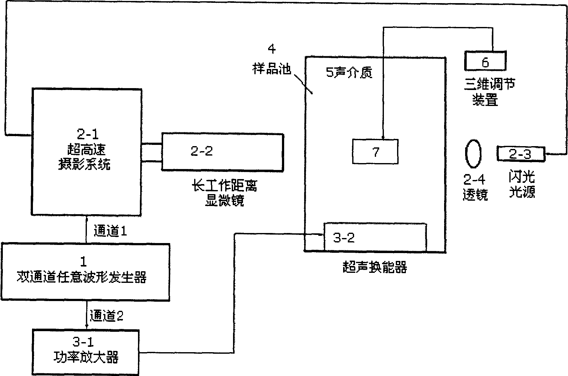
[0117] 1) Reference figure 1 , adjust the position of the tank so that the region of interest is within the field of view of the high-speed camera.

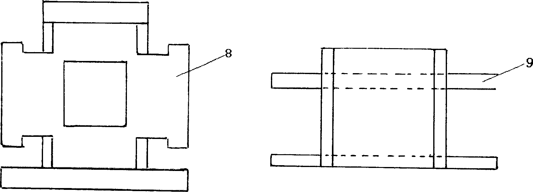
[0118] 2) Use non-degassed water as the acoustic medium, and when observing the coated microbubbles, it is necessary to inject the coated microbubbles (such as SonoVision) into the water. To analyze the behavior of microbubble groups near tissues in the ultrasonic field, it is also necessary to fix the biological tissue in the clamping device (refer to image 3 ), and fix the clamping device on the three-dimensional adjustment device to adjust its position in the sound field. To analyze the behavior of the microbubble group in the microtube in the ultrasonic field, it is necessary to inject a uniform solution containing the coated microbubble into the fiber tube through the flow control device....

Embodiment 2

[0125] Embodiment 2: Combining frequency modulation and amplitude modulation to control the generation and rupture of microbubble groups

[0126] The ultrasound transducer uses a high-intensity focused ultrasound transducer. Change figure 1 The output signal of channel 2 of the dual-channel arbitrary waveform generator is changed from a single-frequency sinusoidal signal to a sinusoidal signal combined with frequency modulation and amplitude modulation, such as Figure 7 shown. In the signal sequence in the figure, a high-amplitude single-frequency sinusoidal signal is first used to generate cavitation microbubbles in the target medium only in the focal region of the high-intensity focused ultrasound field, and then a low-amplitude frequency-modulated sinusoidal signal is used to make the cavitation microbubbles rupture, so as to achieve the purpose of controlling cavitation. Specific steps are as follows:

[0127] 1) Using the method in Example 1, determine the power of t...

Embodiment 3

[0130] Example 3: Single microbubble strain estimation based on microscopic high-speed photography image sequences

[0131] Adopt the method that embodiment 1 introduces, obtain microscopic high-speed photography image sequence, take out wherein two frames (refer to Figure 8 ) to preprocess it, including histogram equalization and edge extraction, we can get Figure 9 The results shown. right Figure 9 The results in ellipse fit to obtain the corresponding centroid position, and use the correlation feedback algorithm based on the genetic algorithm to process the centroid displacement of the microbubble, and the corresponding optical flow diagram of the microbubble movement ( Figure 10 (b)) and strain estimation grayscale image ( Figure 10 (c)).


PUM


Abstract

The present invention discloses analysis system and method of microbubble behavior in biomedicine ultrasonic field based on superhigh speed photograph technology. Specifically, he present invention includes proposing superhigh speed photograph system for observing the microbubbles in ultrasonic field and microscopic superhigh speed photograph system for observing single microbubble; presenting the method of analyzing the microbubble behavior in free field, near tissue and inside microtubule; and presenting the method of controlling microbubbles generation and breaking and estimating microbubble strain.

Description

technical field [0001] The present invention relates to a system and method for analyzing the behavior of microbubbles in an ultrasonic field, more specifically a system and a method for analyzing the behavior of microbubble groups and single microbubbles in a biomedical ultrasonic field by using ultra-high-speed photography technology. Background technique [0002] According to different biomedical applications, ultrasonic fields include medical diagnosis, controlled drug release, sonochemical reaction, heating therapy, ultrasonic lithotripsy, and high-intensity focused ultrasonic fields. The dynamic characteristics of cavitation microbubbles and enveloped microbubbles in ultrasonic field is a general concern in the field of biomedical ultrasound. [0003] Cavitation microbubbles are generated due to acoustic cavitation. Acoustic cavitation can be defined as any phenomenon in which a cavity filled with gas or water vapor oscillates under the a...

Claims


Application Information

Patent Timeline
IPC IPC(8): G01N15/00A61B8/00G01N29/00G06F19/00
Inventor 万明习陈红李晓静崔崤峣
Owner XI AN JIAOTONG UNIV
Why Eureka
Try Eureka