Magnetic high frequency connector

a high-frequency connector and magnet technology, applied in the direction of coupling contact parts, coupling device connections, coupling contact parts, etc., can solve the problems of high-frequency connector damage, signal transmission interruption, and high-frequency connector operation is often interrupted, so as to improve the signal transmission performance and quality of magnetic high-frequency connectors, reduce magnetic field interference, and reduce the effect of magnetic field interferen

Inactive Publication Date: 2019-10-03
QUANTONG TECH CO LTD
View PDF8 Cites 10 Cited by
  • Summary
  • Abstract
  • Description
  • Claims
  • Application Information

AI Technical Summary

Benefits of technology

[0007]Therefore, it is a primary objective of the present invention to overcome the drawbacks of the prior art by providing a magnetic high frequency connector that uses an area with a weaker magnetic field to install the transmission pins, so as to reduce the interference of the magnetic members.
[0008]To achieve the aforementioned objective, the present invention discloses a magnetic high frequency connector comprising a male end portion, a first outer casing, a plurality of first magnetic members, at least one moving terminal, a second outer casing and a female end portion. Wherein, the male end portion has an accommodation space, and the first outer casing covers the male end portion and has a plurality of fixing slots. The first magnetic members are installed in the fixing slots, and two adjacent first magnetic members have a magnetic end spacing and are substantially situated in a heteropolar state, so that a distribution of lines of magnetic force forms at least one weak magnetic area and at least one strong magnetic area in the accommodation space. The moving terminal is installed in the weak magnetic area. The second outer casing has a magnetic portion, and the female end portion is covered by the second outer casing and has at least one fixed terminal, and when the first magnetic members abut against the magnetic portion due to magnetic attraction, the moving terminal and the fixed terminal are electrically coupled to each other. Therefore, when the moving terminal and the fixed terminal are electrically coupled to each other, the magnetic high frequency connector can transmit signals, and the moving terminal disposed in a weak magnetic area with a weaker magnetic field and electrically coupled to the fixed terminal can be operated with minimum electromagnetic interference to reduce the signal transmission interference caused by the first magnetic members, so as to improve the signal transmission performance.
[0009]Preferably, the fixing slots are in a surrounding state and disposed at a side of the male end portion. Therefore, the first magnetic members of the fixing slots disposed on the cross-section of the first outer casing are disposed at the side edge of the moving terminal and around the moving terminal in a surrounding manner. The first magnetic members can abut against the magnetic portion accurately by magnetic attraction to improve the convenience of use of the magnetic high frequency connector and reduce the damage rate of the magnetic high frequency connector.

Problems solved by technology

On the other hand, the operation of the electronic product is often interrupted by tripping over a cable of the high frequency connector.
As a result, the signal transmission is interrupted and the high frequency connector is damaged, or even the electronic product electrically connected to the high frequency connector is damaged.
During the operation of the magnetic high frequency connector, the transmission pins of the male and female connectors are electrically coupled to each other, and the electromagnetic field generated by the magnet and the electronic product will interfere the transmission of the high frequency signal, and the factor causing such interference stems from the magnetic field generated by the magnet of the magnetic high frequency connector.
In other words, the magnetic field generated by the magnet 4 of the connector will interfere with the operation of the transmission pin 41 severely.
Therefore, the signal transmission of the conventional magnetic high frequency connector is interfered by the magnetic field, and the transmission efficiency and quality of the signal are adversely affected.

Method used


Image

  • Magnetic high frequency connector
  • Magnetic high frequency connector
  • Magnetic high frequency connector

Examples


Embodiment Construction

[0028]The above and other objects, features and advantages of this disclosure will become apparent from the following detailed description taken with the accompanying drawings.

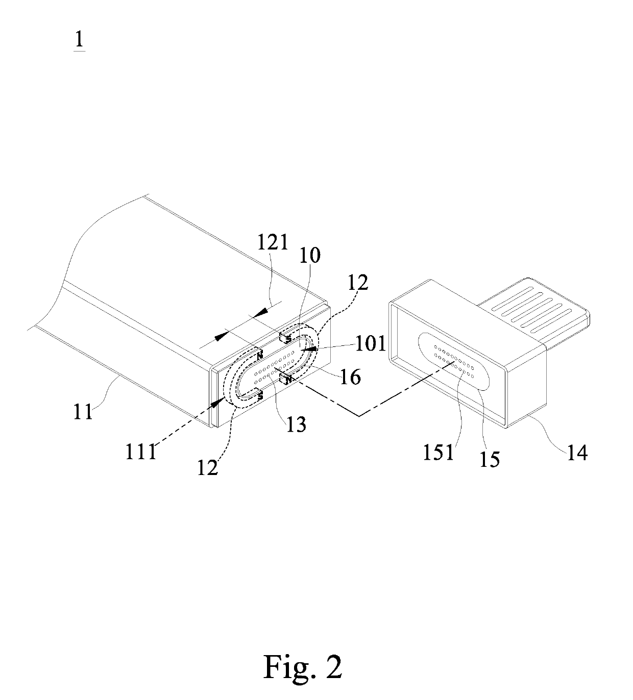
[0029]With reference to FIG. 2 for a perspective view of a magnetic high frequency connector in accordance with a preferred embodiment of the present invention, the magnetic high frequency connector 1 comprises a male end portion 10, a first outer casing 11, a plurality of first magnetic members 12, at least one moving terminal 13, a second outer casing 14 and a female end portion 15. Wherein, the male end portion 10 has an accommodation space 101, and the first outer casing 11 covers the male end portion 10 and has a plurality of fixing slots 111. The first magnetic members 12 are disposed in the fixing slots 111, and two adjacent first magnetic members 12 have a magnetic end spacing 121 in between and substantially situated in a heteropolar state, and a distribution of lines of magnetic force forms at least ...


PUM


Abstract

A magnetic high frequency connector includes a male end portion, a first outer casing, a multiple of first magnetic members, at least one moving terminal, a second outer casing and a female end portion. The male end portion has an accommodation space. The first outer casing covers the male end portion and has a multiple of fixing slots. The first magnetic members are installed in the fixing slots, and two adjacent first magnetic members have a magnetic end spacing and are in a heteropolar state. In the accommodation space, a distribution of lines of magnetic force is formed in at least one weak magnetic area and at least one strong magnetic area. The moving terminal is installed in the weak magnetic area. The second outer casing has a magnetic portion. The female end portion is covered by the second outer casing and has at least one fixed terminal.

Description

CROSS-REFERENCE TO RELATED APPLICATIONS[0001]This non-provisional application claims priority under 35 U.S.C. § 119(a) on Patent Application No(s). 107203952 filed in Taiwan, R.O.C. on Mar. 27, 2018, the entire contents of which are hereby incorporated by reference.FIELD OF THE INVENTION[0002]The present invention relates to the field of a connector, more particularly to a magnetic high frequency connector that is applied to a high frequency connector and electrically coupled by magnetic attraction.BACKGROUND OF THE INVENTION1. Description of the Related Art[0003]As science and technology are developed rapidly, various electronic products are developed to assist our life and work. Most electronic products require a connector to connect to a power supply in order to use the electronic products or electrically connect to another electronic product in order to transmit digital data. The connector is widely used in the electronic products in different areas including the industrial, med...

Claims


Application Information

Patent Timeline
Patent Type & Authority Applications(United States)
IPC IPC(8): H01R13/62H01R24/40H01R13/627
CPCH01R24/40H01R13/627H01R13/6205H01R2107/00H01R13/24H01R13/6461
Inventor LAN, LI-CHUN
Owner QUANTONG TECH CO LTD
Why Eureka
Try Eureka