Hybrid Power Boost Charging With Peak Power Protection
Active Publication Date: 2019-10-03
INTEL CORP
View PDF6 Cites 4 Cited by
- Summary
- Abstract
- Description
- Claims
- Application Information
AI Technical Summary
Benefits of technology
The patent text discusses a problem in mobile computing systems where the battery voltage can drop below a minimum level, limiting the peak power of the system and requiring larger batteries to maintain functionality. This problem is caused by resistance and voltage droop between the battery cells and the system's voltage regulator. The text proposes a solution using hybrid power boost (HPB) charging with peak power protection to increase the battery's ability to handle peak power demands. The technical effects of this solution include improved battery performance and reduced battery size requirements.
Problems solved by technology
The mobile computing industry is continually moving toward smaller form factors, while at the same time the SoC (System On Chip) is consuming more power, bringing intense thermal cooling complexity.
This resistance and voltage droop can limit peak platform power, particularly in situations where the battery is not fully charged.
Method used
View moreImage
Smart ImageViewing Examples


Examples
example 2
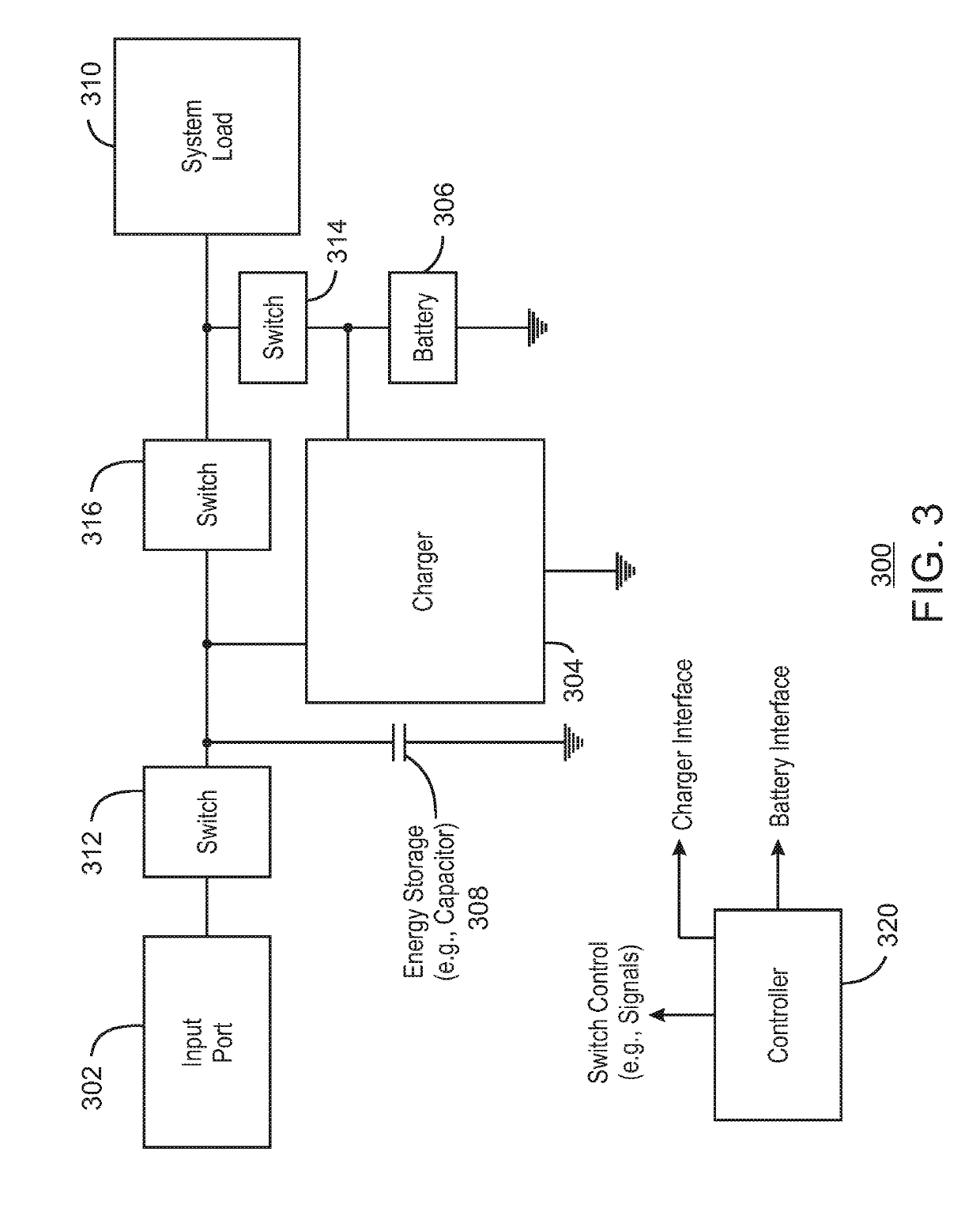
[0112 includes the subject matter of example 1. In example 2, a second switch is to couple the battery to the system load and is to decouple the battery from the system load.
example 3
[0113 includes the subject matter of any of examples 1-2. In example 3, a controller is to control the switch.
example 4
[0114 includes the subject matter of any of examples 1-3. In example 4, when a device is coupled to an input port of the system the switch is on to connect the system load to an input voltage.
Login to View More PUM
 Abstract
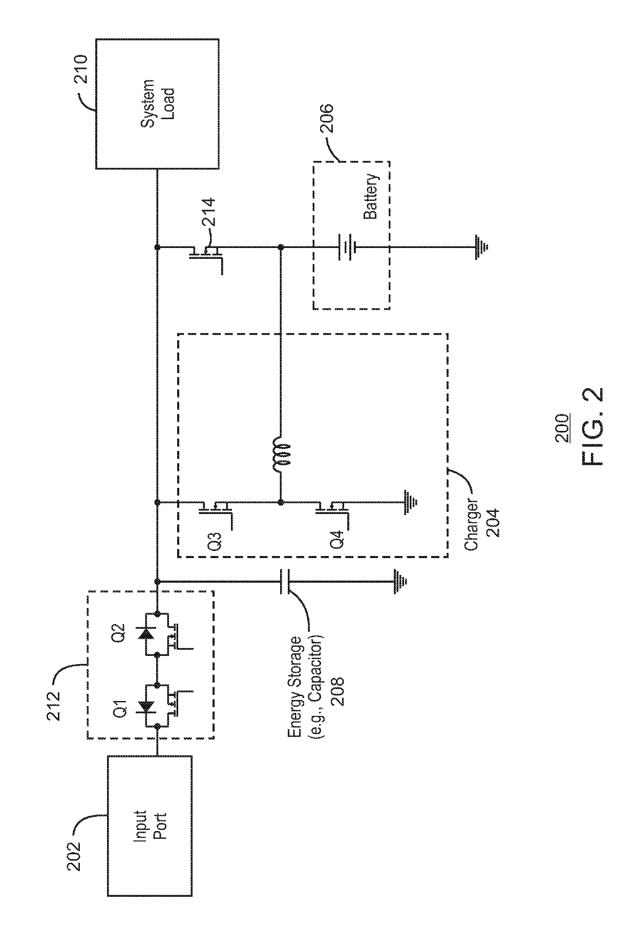
In some examples, a hybrid power boost peak power protection system includes an energy storage, a hybrid power boost charger to charge a battery, and a switch to couple a system load to the energy storage and to decouple the system load from the energy storage.
Description
RELATED APPLICATIONS[0001]This application is related to U.S. patent application Ser. No. 15 / 477,046 filed on Apr. 1, 2017 and entitled “Power Management And Protection”. This application is also related to U.S. patent application Ser. No. 15 / 466,498 filed on Mar. 22, 2017 and entitled “Mechanism To Extend The Peak Power Capability Of a Mobile Platform”.TECHNICAL FIELD[0002]This disclosure relates generally to hybrid power boost (HPB) charging with peak power protection.BACKGROUND[0003]The mobile computing industry is continually moving toward smaller form factors, while at the same time the SoC (System On Chip) is consuming more power, bringing intense thermal cooling complexity. The peak power requirement for the SoC is increasing almost exponentially along with the rising peak power of the rest of the system.[0004]Many computing systems (for example, portable mobile systems or client systems) need to maintain a system voltage above a certain level (for example, above a Vmin level...
Claims
Login to View More Application Information
Patent Timeline
 IPC IPC(8): H02J7/00
CPCH02J7/007H02J7/0026H02J2007/0095H02J7/0068H02J2207/20H02J2207/10
Inventor HAND, TEALUAN-ZO-LI, ALEXANDER B.
Owner INTEL CORP