
Display control apparatus and control method

Active Publication Date: 2019-10-03
CANON KK
View PDF0 Cites 3 Cited by
  • Summary
  • Abstract
  • Description
  • Claims
  • Application Information

AI Technical Summary

Benefits of technology

The present invention aims to provide a technique to prevent the user from experiencing irritation when they move the display range of a wide visual field image in the display control apparatus. This helps to improve the user experience and make the operation more comfortable.

Problems solved by technology

However, if this display control is performed, in some cases the display may not follow the user operation, when the range, including the vertex (zenith or nadir) of the wide visual field image in the vertical direction is displayed on the display.
This inconsistent relationship of the directions may irritate the user.

Method used


Image

  • Display control apparatus and control method
  • Display control apparatus and control method
  • Display control apparatus and control method

Examples


example 1

[0084]The operation of the electronic device 100 according to Example 1 of the present invention will be described with reference to FIG. 4 to FIGS. 8A to 8H.

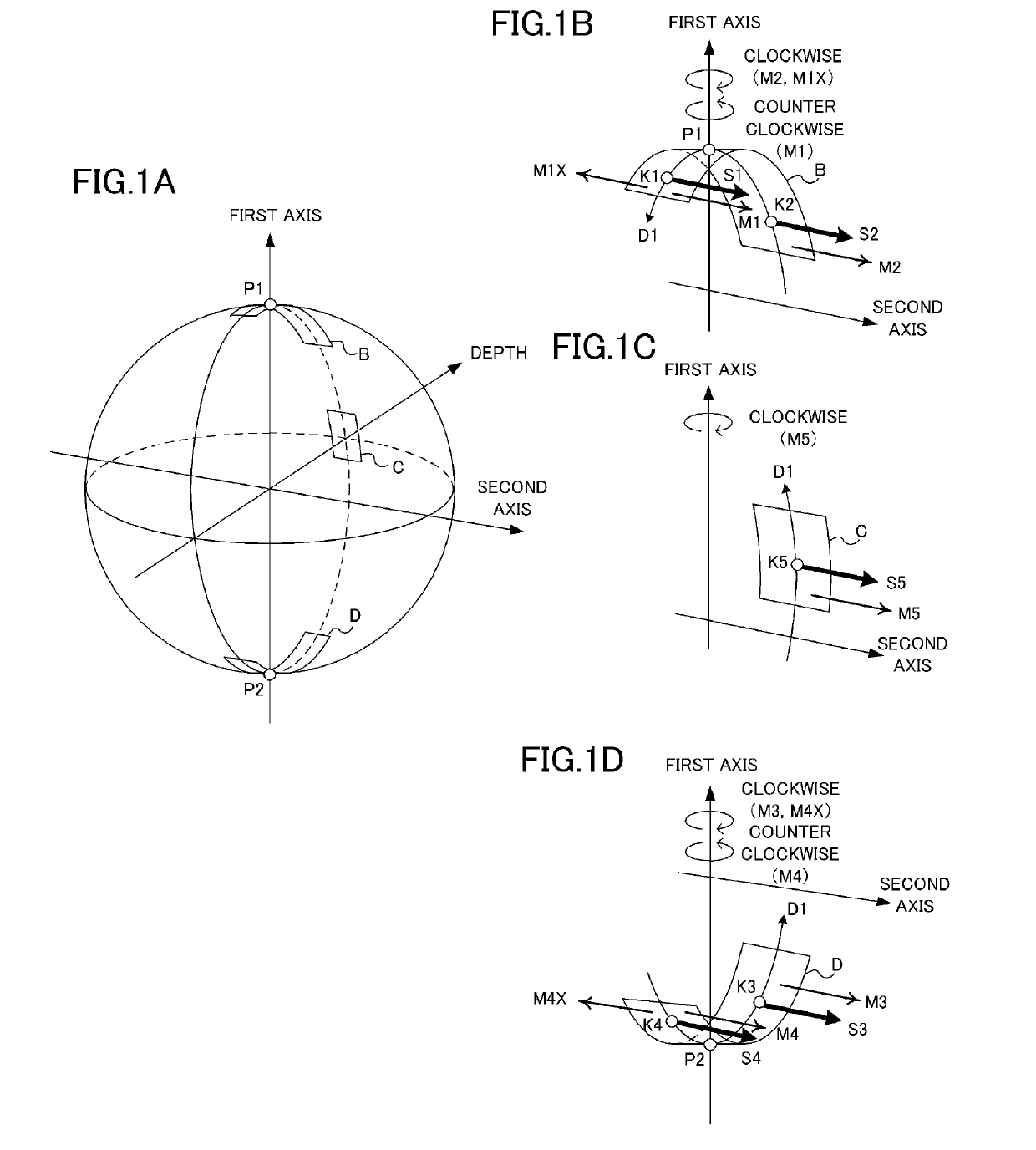
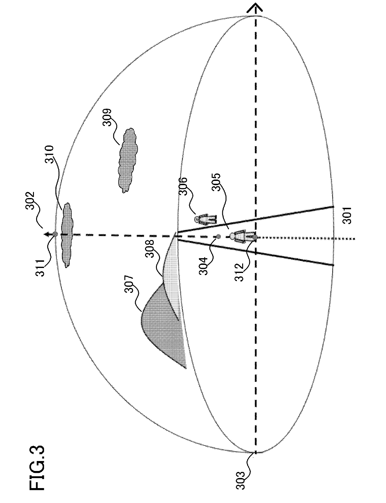
[0085]The characteristic of Example 1 is the display control in the state where the range of the wide visual field image 301, including the zenith 311 or the nadir 312, which is a vertex in the first axis direction, is displayed on the display 105. In other words, the characteristic thereof is the display control in the case when the moving operation in the horizontal direction (second axis direction) is input to the touch panel 106a. The CPU 101 performs the display control to change the display range of the wide visual field image displayed on the display unit by rotating the wide visual field image 301 around the first axis. The CPU 101 determines the direction of rotating the wide visual field image 301 around the first axis in accordance with the positional relationship between the start point (Touch-Down position) of the ...

example 2

[0176]The operation of the electronic device 100 according to Example 2 of the present invention will be described with reference to FIG. 9 andFIGS. 10A to 10H. The characteristic of Example 2 is the display control when the moving operation in the horizontal direction (second axis direction) is input to the touch panel 106a in the state where the range of the wide visual field image 301, including a vertex in the first axis direction, the zenith 311 or the nadir 312, that is, is displayed on the display 105. The CPU 101 changes the direction of rotating the wide visual field image 301 around the first axis, in accordance with the positional relationship between the start point (Touch-Down position) of the slide operation, which is the moving operation in the horizontal direction, and the vertex (the zenith 311 or the nadir 312). In concrete terms, when the display range includes the zenith 311, the CPU 101 determines whether the start point of the slide operation is above the zenit...


PUM


Abstract

Provided is a display control apparatus to perform operations of units including a display control unit configured to display a partial range of the wide visual field image and a control unit. The control unit changes the display range of the wide visual field image by rotating the display range clockwise or counterclockwise around the first axis in response to input of a moving operation in a first direction or in a second direction opposite to the first direction. The control unit changes the display range by rotating the display range in a rotation direction around the first axis in response to input of a moving operation in the first direction, wherein the rotation direction differs based on a positional relationship between a start point of the moving operation and the center position with respect to a axis direction vertical to the first direction.

Description

BACKGROUND OF THE INVENTIONField of the Invention[0001]The present invention relates to a display control apparatus, and a control method, a program and a storage medium therefor.Description of the Related Art[0002]A technique that is becoming common is mapping an image captured by an omni-azimuth camera (omni-directional camera) onto the surface of a virtual sphere, so as to display an image as if viewing the image mapped onto the surface of the sphere from a viewpoint located at the center of the sphere. Hereafter an image mapped onto a virtual spherical surface is called a “wide visual field image”. An available technique to display a wide visual field image is a technique of changing a range of the wide visual field image to be displayed on the display, in accordance with a user input operation using a pointing device, attitude information of a head mount display and the like. Japanese Patent Application Publication NO. 2017-107549 discloses a technique in which a display region...

Claims


Application Information

Patent Timeline
IPC IPC(8): H04N13/398H04N5/232H04N13/349
CPCG06F3/033H04N13/398H04N13/349H04N5/23238G06F3/0488G06F3/04815G06F3/04845G06F3/04883G06F3/147G09G3/20G06T3/08G06F3/0485H04N23/698
Inventor KOYAMA, JUN
Owner CANON KK
Features
  • Generate Ideas
  • Intellectual Property
  • Life Sciences
  • Materials
  • Tech Scout
  • Unparalleled Data Quality
  • Higher Quality Content
  • 60% Fewer Hallucinations
Learn More