
Discharge head, and liquid dispenser comprising such a discharge head

Active Publication Date: 2019-10-10
APTAR RADOLFZELL
View PDF0 Cites 2 Cited by
  • Summary
  • Abstract
  • Description
  • Claims
  • Application Information

AI Technical Summary

Benefits of technology

The invention is a discharge head with a dynamic throttle device that adjusts its flow resistance based on actuation parameters. This allows for a reduction in the size of the throttle channel's free cross section with higher pressure or greater liquid flow. The device can also be used with cosmetic or pharmaceutical liquids, such as make-up products and creams, for better discharge and filling of wrinkles. The main technical effects of this invention include improved discharge control, reduced pressure drop, and improved accuracy in liquid discharge.

Problems solved by technology

However, according to the manner of the pressure application, it is possible for a user to influence the pressure directly and thus, in light of the application purpose, also to subject the liquid to an excessive pressure, for example by the force with which a squeeze bottle, serving as a liquid store, is compressed.
Alternatively, a pressure can be generated, which leads to a spray pattern with excessively fine droplets.
However, the effect of such a throttle is then that the actuation always has to be realized by a fairly large force.

Method used


Image

  • Discharge head, and liquid dispenser comprising such a discharge head
  • Discharge head, and liquid dispenser comprising such a discharge head
  • Discharge head, and liquid dispenser comprising such a discharge head

Examples


Embodiment Construction

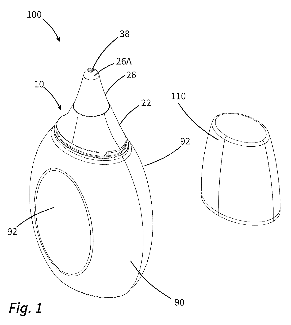
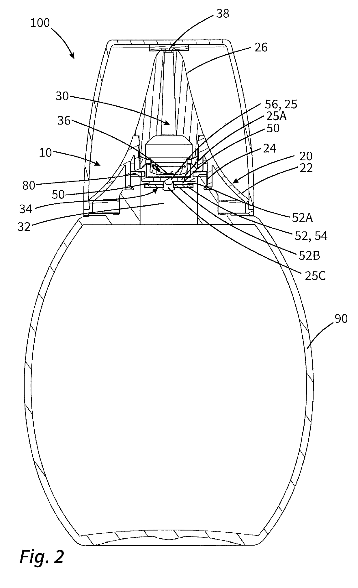
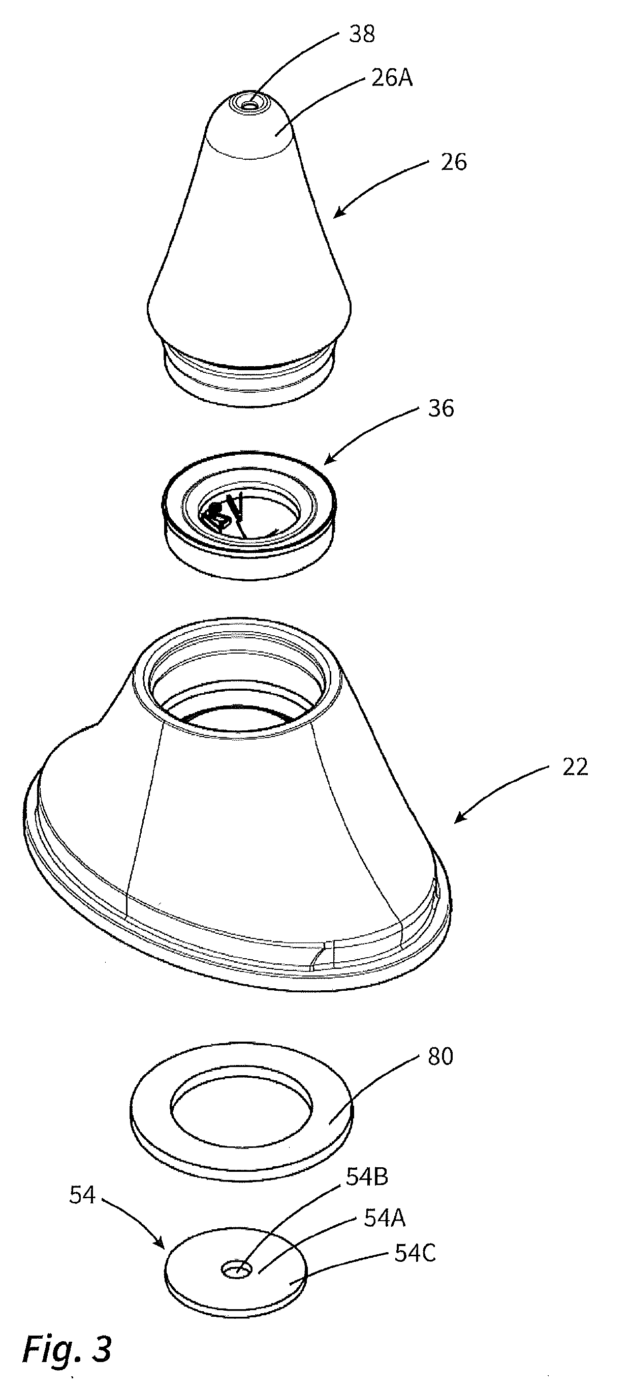
[0072]FIG. 1 shows a liquid dispenser 100 according to the invention, which is designed in the manner of a drop dispenser.

[0073]Said liquid dispenser 100 has a liquid store 90, which is designed in the form of a squeeze bottle, and a discharge head 10 mounted thereon, at which a discharge opening 38 is provided. To close the liquid dispenser, a cap 110 is provided.

[0074]The liquid dispenser serves for releasing, in drop form, drops, for example of cosmetic liquids such as oils, make-up, filler or the like. In this case, for actuation as intended, the entire dispenser is positioned more or less upside down, with the discharge opening 38 pointing downward, and, in this position, the liquid store 90 is, on opposite sides in the region of actuation surfaces 92, subjected to force and compressed such that the liquid contained in the liquid store is subjected to pressure and is conveyed to the discharge opening 38. Here, the liquid is gathered at a drop formation surface 26A, which surrou...


PUM


Abstract

Discharge head for a liquid dispenser including a housing, a coupling device for attachment to a liquid store, a discharge opening through which liquid is dispensed and an outlet channel extending from an inlet region, pointing in the direction of the liquid store, up to the discharge opening and via which the discharge opening is supplied with liquid. A throttle device is arranged in the outlet channel and includes a throttle channel for reducing liquid pressure and / or liquid flow through the throttle device. The throttle device is designed in the form of a dynamic throttle device, in which a free cross section of the throttle channel is reduced in size with increasing pressure prevailing at the throttle device, or with greater liquid flow flowing through the throttle device.

Description

FIELD OF APPLICATION AND PRIOR ART[0001]The invention relates to a discharge head for a liquid dispenser, and to a liquid dispenser with such a discharge head.[0002]A discharge head of the type in question has a housing and a coupling device for attachment to a liquid store. It also has a discharge opening through which liquid is able to be dispensed into a surrounding atmosphere, and an outlet channel which extends from an inlet region, pointing in the direction of the liquid store, up to the discharge opening and by means of which the discharge opening is able to be supplied with liquid.[0003]With a dispenser of the type in question and a discharge head of the type in question, it is provided that the liquid in the liquid store, or in a pressure chamber separate therefrom, is subjected to pressure in order to be conveyed by way of this pressure through the outlet channel in the direction of the discharge opening. However, according to the manner of the pressure application, it is ...

Claims


Application Information

Patent Timeline
IPC IPC(8): B65D47/18B65D47/08B65D47/20B05B11/00
CPCB05B11/3073B05B11/0062B65D47/18B65D47/0804B65D47/2031B05B11/1073
Inventor BAUMANN, TOBIASBRUDER, THOMAS
Owner APTAR RADOLFZELL
Features
  • Generate Ideas
  • Intellectual Property
  • Life Sciences
  • Materials
  • Tech Scout
  • Unparalleled Data Quality
  • Higher Quality Content
  • 60% Fewer Hallucinations
Learn More