
Virtual sensor for water content in oil circuit

Active Publication Date: 2020-05-21
FEILER WOLFGANG
View PDF0 Cites 3 Cited by
  • Summary
  • Abstract
  • Description
  • Claims
  • Application Information

AI Technical Summary

Benefits of technology

The present invention proposes a method for monitoring an oil-injected screw compressor by calculating the water inlet mass flow and the water outlet mass flow, and the difference between them, to determine the formation of condensate in the oil circuit. This method helps to prevent damage to the compressor and ensures optimal performance. The invention also takes into account the effects of temperature, humidity, and the intake and delivery capacity of the screw compressor. The invention provides a better understanding of the oil circuit and the factors that affect it, allowing for better control and regulation of the compressor.

Problems solved by technology

This can lead to damage.
For example, corrosion can occur in the screw compressor.

Method used


Image

  • Virtual sensor for water content in oil circuit
  • Virtual sensor for water content in oil circuit
  • Virtual sensor for water content in oil circuit

Examples


Embodiment Construction

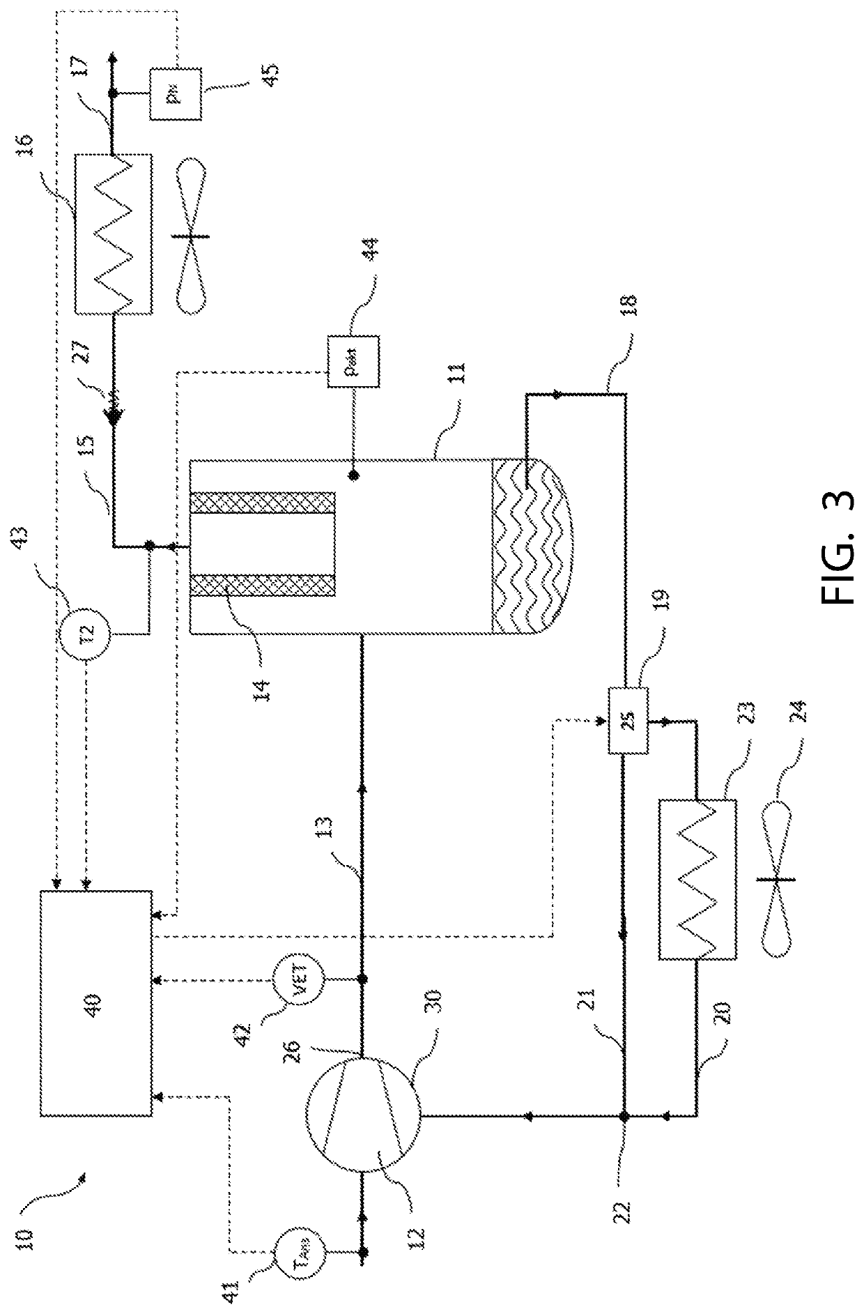
[0059]FIG. 3 shows a block diagram of a screw compressor 10 comprising a compressor block 30 and an oil separator 11. The screw compressor 10 also has a compression chamber 12 in the compressor block 30. Compressed air reaches the oil separator 11 via a first compressed-air line 13. An oil filter 14 is provided in the oil separator tank 11. The compressed air, which is fed via the first compressed-air line 13 into the oil separator tank 11, passes through the oil filter 14 and is fed via a second compressed-air line 15 to an aftercooler 16 and from there via a third compressed-air line 17 to a useful application, e.g. a line network buffered via a compressed-air tank in an industrial plant.

[0060]The oil separated in the oil separator tank 11 is returned via a return line 18 to the screw compressor 10 where it is injected into the compression chamber 12 for cooling, sealing and lubrication. The return line is divided into a first partial line 20 and a second partial line 21 at a bran...


PUM


Abstract

A method for monitoring an oil-injected screw compressor configured to compress aspirated air by returning oil from an oil separator vessel (11) to a compression chamber (12) of a compressor block (30), for condensate formation in the oil circuit due to a too low compression discharge temperature (VET), determines a water inlet mass flow {dot over (m)}ein(t) and a water outlet mass flow {dot over (m)}aus(t) for a point in time t and determines generated condensate flow Δ{dot over (m)}w(t)={dot over (m)}ein(t)−{dot over (m)}aus(t) on the basis of difference formation.

Description

CROSS REFERENCE TO RELATED APPLICATIONS[0001]Applicant claims priority under 35 U.S.C. § 119 of European Application No. 18207118.3 filed Nov. 19, 2018, the disclosure of which is incorporated by reference.BACKGROUND OF THE INVENTION1. Field of the Invention[0002]The invention relates to a method for monitoring an oil-injected screw compressor, in which oil from an oil separator tank is returned to a compression chamber of a compressor block, following an unintentional cold run in which condensation occurs due to a too low compression discharge temperature.2. Description of the Related Art[0003]With oil-injected screw compressors, ambient air is compressed to a higher pressure. The compression process takes place inside the screw compressor block. This generates compression heat. Oil is injected into the screw compressor block to prevent the temperature of the compressed air from rising too high. The oil absorbs part of the compression heat and heats up in the process. The temperatu...

Claims


Application Information

Patent Timeline
IPC IPC(8): F04C28/28G01N11/04F04C29/02
CPCF04C2240/81F04C29/028G01N11/04F04C29/025F04C2270/78F04C28/28G01F1/86G01F1/88F04C18/16F04C29/026
Inventor FEILER, WOLFGANG
Owner FEILER WOLFGANG
Features
  • Generate Ideas
  • Intellectual Property
  • Life Sciences
  • Materials
  • Tech Scout
  • Unparalleled Data Quality
  • Higher Quality Content
  • 60% Fewer Hallucinations
Learn More