
Gaming machine including brushless motor system

Active Publication Date: 2019-10-10
ARISTOCRAT TECH AUSTRALIA PTY LTD
View PDF0 Cites 18 Cited by
  • Summary
  • Abstract
  • Description
  • Claims
  • Application Information

AI Technical Summary

Benefits of technology

The patent describes a brushless motor system for a mechanical reel gaming machine. The system includes a reel and a reel frame rotationally attached to the reel hub. The reel frame displays symbols associated with the game and a permanent magnet (PM) rotor attached to the reel frame. The system also includes a stator with stator coils mounted parallel to the surface of the PM rotor. The stator causes the PM rotor to rotate without direct contact between them, thereby causing the display of symbols during the game. The system and method improve the operation of the mechanical reel gaming machine by making it more efficient and reliable.

Problems solved by technology

Therefore, without the proper stepping algorithms, the poles of the stepper motors may slip and the reels lose their position, resulting in a tilt error of the gaming machines.
The holding of the mechanical load is accomplished by keeping the winding current high (even though the stepper motors' rotor is aligned with the stepper motors' stator) which wastes a lot of energy because no torque is generated unless the mechanical load tries to turn out of position.
Stepper motors are also disadvantageous because they draw substantial power regardless of load causing low efficiency, their torque drops rapidly with speed (the direction of the torque is inverse of the speed), their accuracy is low (e.g., 1:200 at full load, 1:2000 at light loads), they are prone to resonances (e.g., they require microstepping to move smoothly), they do not provide feedback to indicate missed steps, they have a low torque to inertia ratio that impedes acceleration of loads rapidly, their temperature substantially increases at high performance configurations, they do not “pick up” after momentary overload, they are audibly very noisy at moderate to high speeds, and they generate a low output power compared to their size and weight.

Method used


Image

  • Gaming machine including brushless motor system
  • Gaming machine including brushless motor system
  • Gaming machine including brushless motor system

Examples


Embodiment Construction

[0017]The following detailed description illustrates embodiments of the invention by way of example and not by way of limitation. It is contemplated that the invention has general application to gaming machine embodiments providing player comfort and ergonomic considerations in industrial, commercial, and residential applications.

[0018]The following description refers to the accompanying drawings, in which, in the absence of a contrary representation, the same numbers in different drawings represent similar elements.

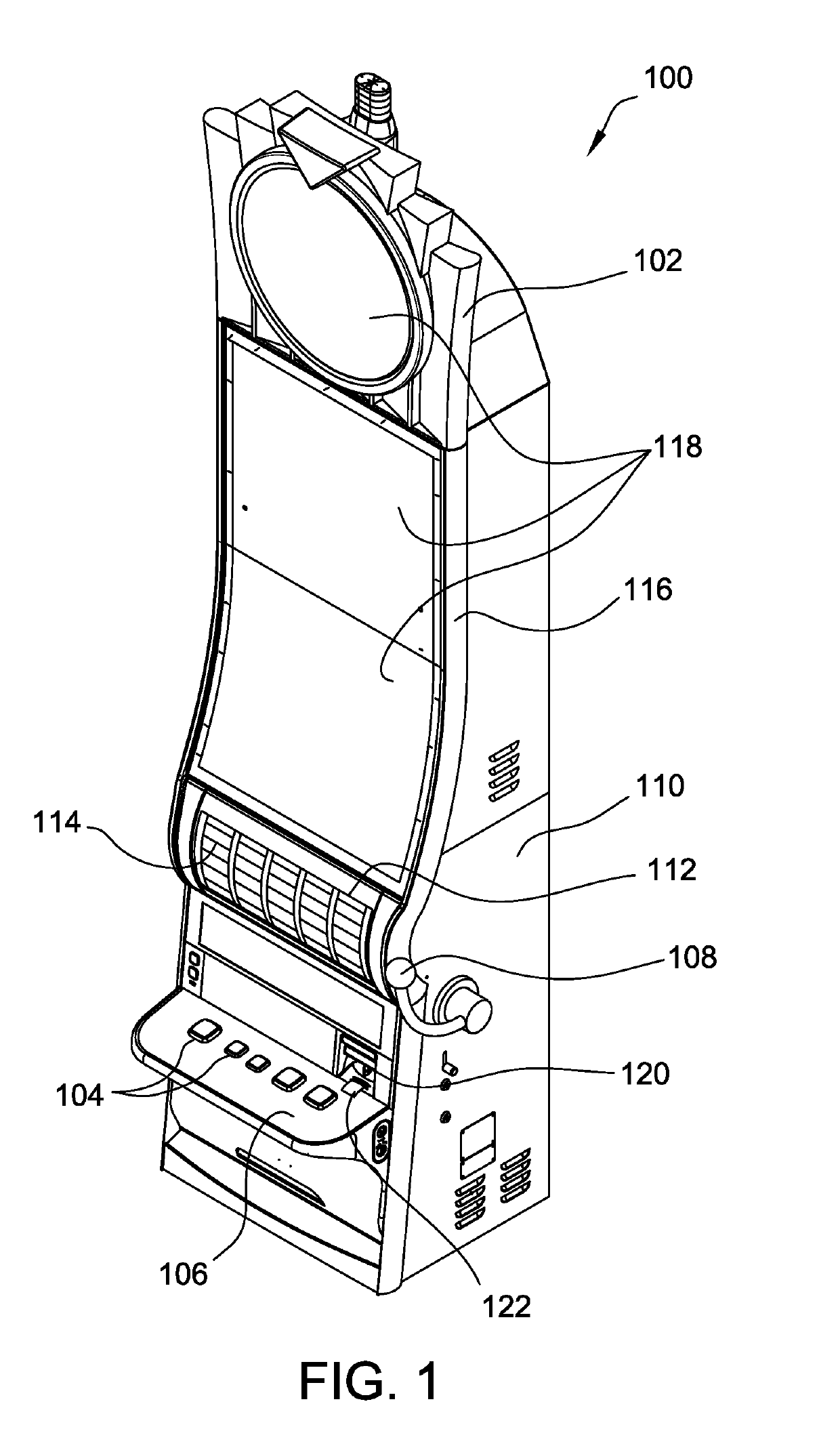
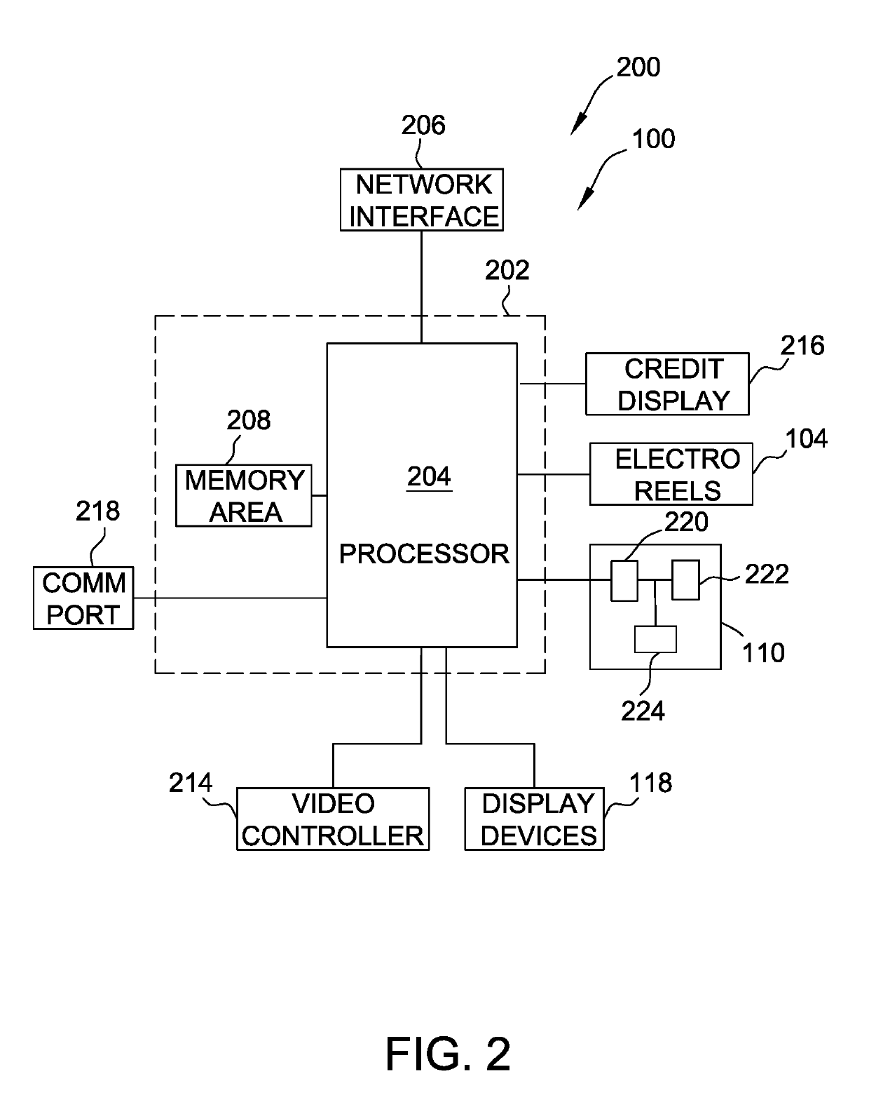
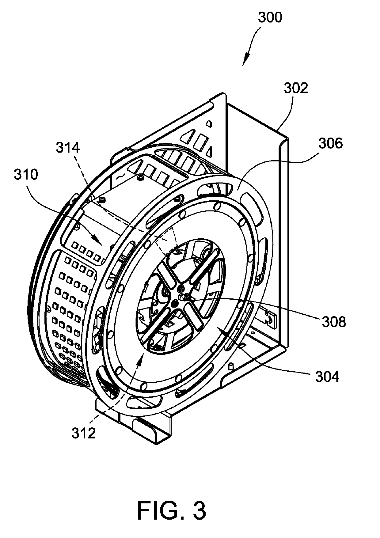
[0019]A mechanical reel gaming machine is described herein that includes a brushless motor system for improving operations of the gaming machine. As described herein, the brushless motor system includes, among other components, an inductively-coupled drive mechanism for a mechanical reel that includes a rotor and a stator. The rotor is integrated into the frame of the mechanical reel, and the stator is mounted to a stationary frame of the gaming machine. That is, the bru...


PUM


Abstract

A brushless motor system for use with a mechanical reel gaming machine is provided. The brushless motor system includes a reel hub and a reel frame rotationally attached to a center shaft of the reel hub. The brushless motor system also includes a permanent magnet (PM) rotor attached to the reel frame and including a plurality of permanent magnets attached to the PM rotor. The brushless motor system further includes a stator including stator coils attached to the reel hub, the plurality of stator coils are mounted parallel to a surface of the PM rotor at a separation distance. The stator causes the PM rotor to rotate during activation of the stator without direct contact between the stator and the rotor, thereby causing the display of one or more symbols of the plurality of symbols during the wagering game based on the rotation.

Description

BACKGROUND[0001]The present disclosure relates generally to gaming machines and wagering and, more particularly, to a gaming machine that includes a brushless motor system for improving operations of the gaming machines.[0002]At least some known gaming machines include stepper motors that enable reels of the gaming machines to rotate. The rotating reels are mechanical spinning reels housed inside the machines that are spun and randomly stopped to place images, symbols, or indicia on the reels in alignment to determine payouts. Drive mechanisms for the reels have developed overtime to the point where the rotation and, in particular, the stopped position of the reels is precisely controlled to manage the allocation of payouts. More recently, electronic gaming machines have been used to simulate spinning reels using computer generated graphics and electronics. However notwithstanding the existence of electronic gaming machines, players are still attracted to, and enjoy, gaming machines...

Claims


Application Information

Patent Timeline
IPC IPC(8): G07F17/32G07F17/34
CPCG07F17/34G07F17/3213
Inventor LAMB, WILLIAMDU, THACHLITER, CHARLES A.
Owner ARISTOCRAT TECH AUSTRALIA PTY LTD
Learn More