Electromagnetic relay

a technology of electromagnetic relays and relays, applied in electromagnetic relay details, contact, electrical equipment, etc., can solve problems such as significant deterioration of the insulating property of electromagnetic relays

Active Publication Date: 2019-10-10
ORMON CORP
View PDF0 Cites 11 Cited by
  • Summary
  • Abstract
  • Description
  • Claims
  • Application Information

AI Technical Summary

Benefits of technology

[0007]Therefore, it is an object of the present invention to provide an electromagnetic relay capable of avoiding formation of a short-circuit path between a pair of fixed terminals due to a scattered powder and ensuring insulation.
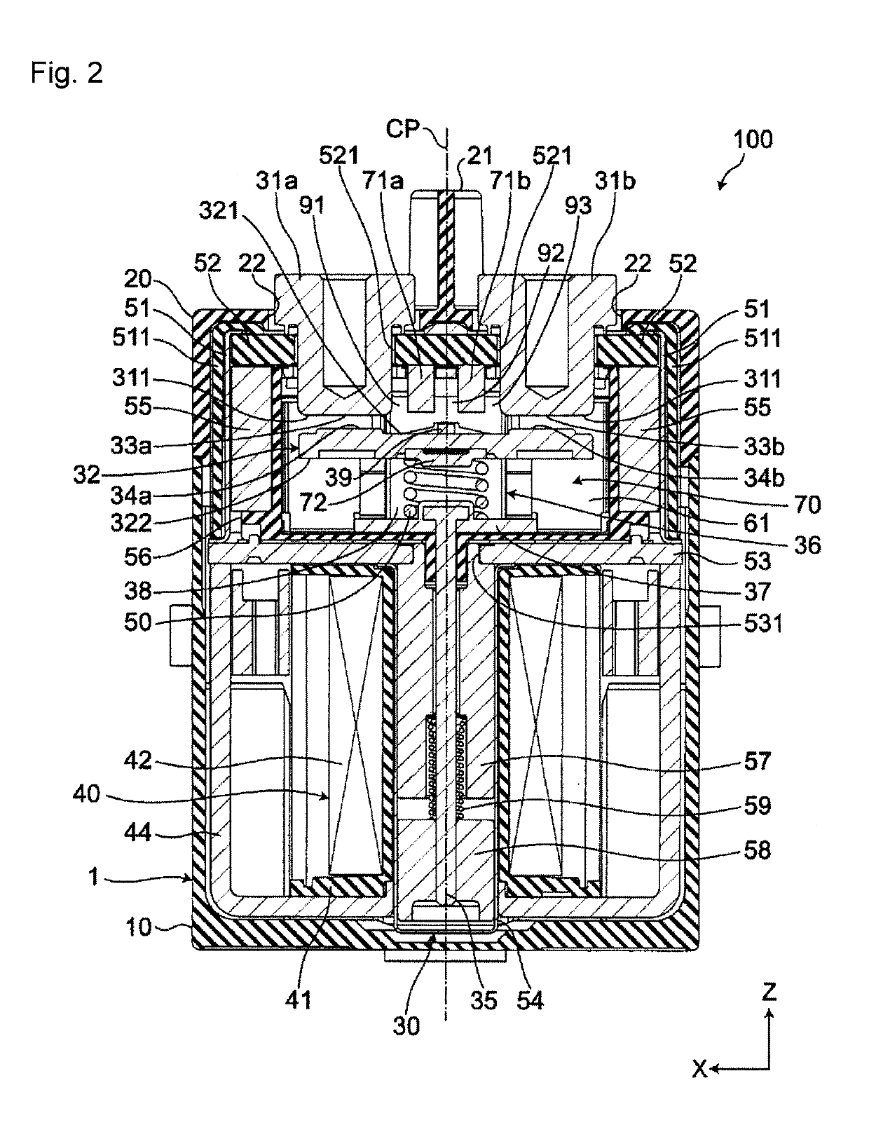
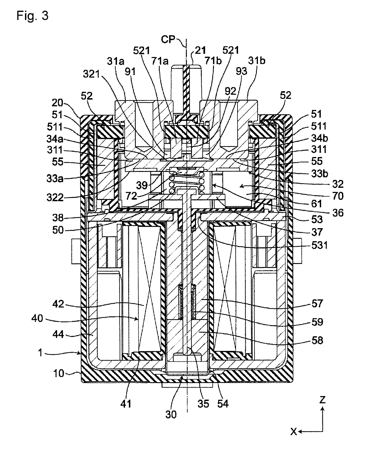
[0009]According to the electromagnetic relay according to one or more embodiments of the present invention, with the plurality of first electromagnetic members provided, it is possible to avoid formation of a short-circuit path between a pair of fixed terminals due to a scattered powder and ensure the insulation between the pair of fixed terminals and the plurality of first electromagnetic members being disposed electrically independently of each other, with a gap provided therebetween in the arrangement direction of the pair of fixed terminals, between the pair of fixed terminals in the housing and being fixed to the pair of fixed terminals in an electrically independent manner.

Problems solved by technology

When this scattered powder is accumulated between the pair of fixed terminals and the first electromagnetic member, a short-circuit path is formed between the pair of fixed terminals via the scattered powder since the scattered powder is conductive, thereby causing significant deterioration in insulating property of the electromagnetic relay.

Method used


Image

  • Electromagnetic relay
  • Electromagnetic relay
  • Electromagnetic relay

Examples


Embodiment Construction

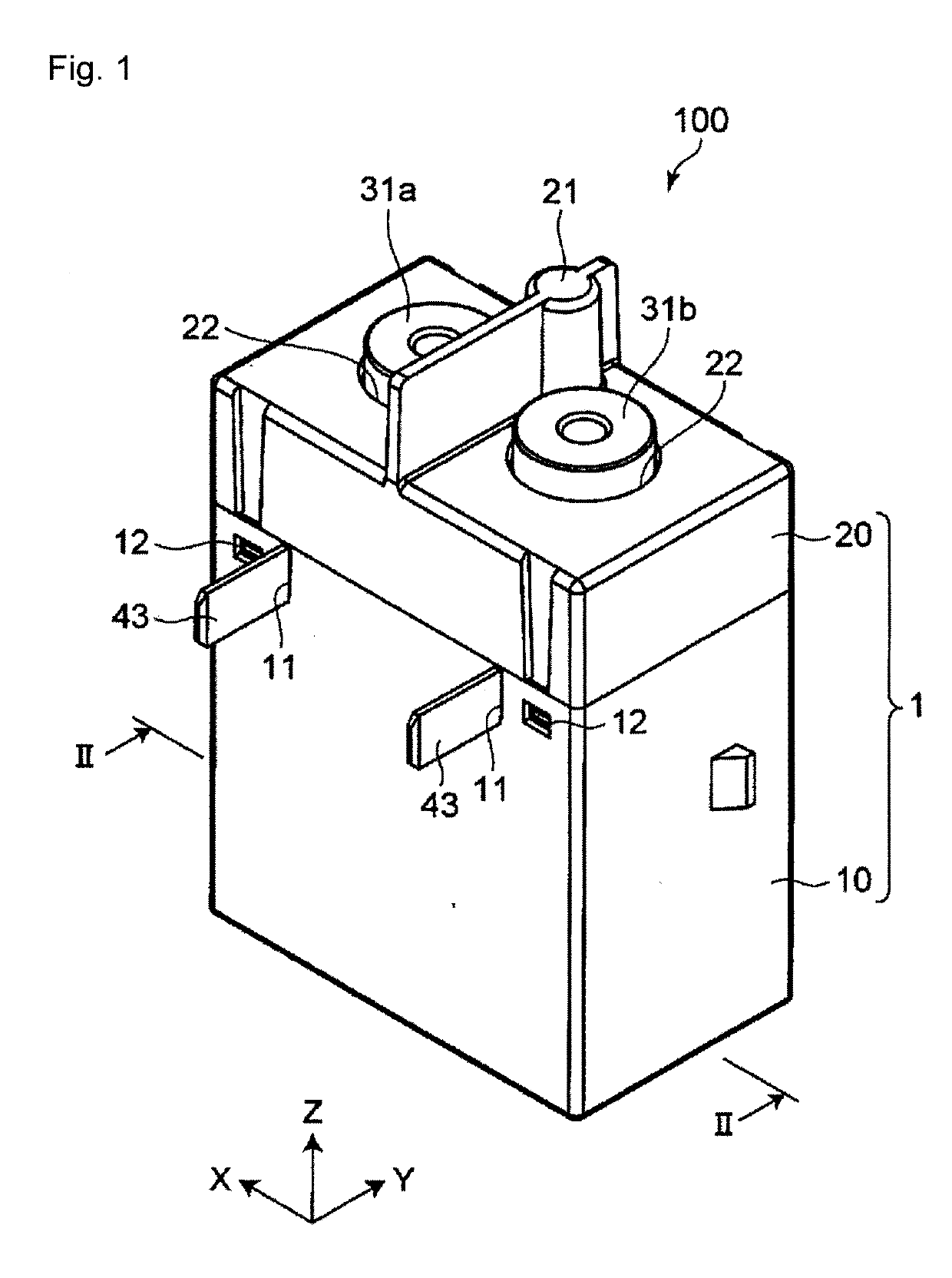
[0015]Hereinafter, embodiments of the present invention will be described with reference to the accompanying drawings. In the following description, terms (e.g., terms including “upper”, “lower”, “right”, “left”, “side”, and “end”) indicating specific directions or positions are used as necessary, but the use of these terms is for facilitating understanding of the invention with reference to the drawings, and the technical scope of the present invention is not limited by the meaning of these terms. The following description is merely exemplary in nature and not intended to limit the present invention, its application, or its usage. Further, the drawings are schematic, and ratios of dimensions or the like do not necessarily agree with actual ones. In embodiments of the invention, numerous specific details are set forth in order to provide a more thorough understanding of the invention. However, it will be apparent to one of ordinary skill in the art that the invention may be practice...


PUM


Abstract

An electromagnetic relay includes a box-shaped insulating housing in which a closed space is formed, a pair of fixed terminals fixed to the housing electrically independently of each other and each having a fixed contact placement surface in the closed space, a plate-shaped conductive movable contactor that is provided in the closed space, has a first surface facing the fixed contact placement surfaces of the pair of fixed terminals, and is movably disposed such that the first surface approaches and separates from the fixed contact placement surfaces of the pair of fixed terminals, a pair of fixed contacts respectively provided on the fixed contact placement surfaces of the pair of fixed terminals, and a pair of movable contacts that is respectively provided on the first surface of the movable contactor and respectively face the pair of fixed contacts.

Description

BACKGROUNDTechnical Field[0001]The present invention relates to an electromagnetic relay.Related Art[0002]An electromagnetic relay disclosed in Patent Document 1 includes: a housing having a closed space therein; a pair of fixed terminals electrically fixed to the housing so as to be electrically independent of each other; and a plate-shaped movable contactor which is provided in the closed space, faces a pair of fixed terminals, and is movable so as to approach or separate from the pair of fixed terminals. A fixed contact is fixed to each of the tips, located in the closed space, of the pair of fixed terminals. A pair of movable contacts arranged so as to respectively face the pair of fixed contacts are fixed to the movable contactor.[0003]In addition, the electromagnetic relay includes a first electromagnetic member electrically independently fixed to the pair of fixed terminals between the pair of fixed terminals of the housing, and a second electromagnetic member that faces one ...

Claims


Application Information

Patent Timeline
Patent Type & Authority Applications(United States)
IPC IPC(8): H01H50/42H01H50/18H01H50/54
CPCH01H50/641H01H50/18H01H2050/362H01H50/42H01H50/546H01H1/64H01H50/54H01H50/56H01H9/443H01H1/54H01H50/14
Inventor MINOWA, RYOTAMORI, SHINGOKAKIMOTO, TOSHIYUKIIKEMOTO, KAZUHIRO
Owner ORMON CORP
Why Eureka
Try Eureka