Electromagnetic crimp terminal, manufacturing method of electromagnetic crimp terminal, and connecting terminal

a technology manufacturing method, which is applied in the direction of manufacturing tools, contact member manufacturing, and capacitors, etc., to achieve the effect of reducing the manufacturing reducing the type of terminal plate, and lowering the cost of electromagnetic crimp terminal

Active Publication Date: 2019-10-17
YAZAKI CORP
View PDF19 Cites 0 Cited by
  • Summary
  • Abstract
  • Description
  • Claims
  • Application Information

AI Technical Summary

Benefits of technology

[0014]Since the vicinity of one side edge and the vicinity of the other side edge overlap with each other in the crimped portion in the electromagnetic crimp terminal according to the present disclosure, crimped portions with various diameters are formed from a common terminal plate. Thus, the cost of the electromagnetic crimp terminal is lowered by promoting common use of members.
[0015]In addition, since the cylindrical portion can be increased and reduced to various diameters by increasing or reducing the overlapped area in the method for manufacturing the electromagnetic crimp terminal according to the present disclosure, a common terminal plate can be crimped onto the electric wire having conductor portions with various outer diameters. Therefore, since the types of terminal plate can be reduced and the conductor portions with various diameters can be crimped onto the common terminal plate, the common use of members is promoted, and the manufacturing cost of the electromagnetic crimp terminal can be reduced.
[0016]In addition, since the diameter of the cylindrical portion is reduced by an electromagnetic force in respond to a fact that it is difficult to crimp the electric wire uniformly in a circumferential direction in the mechanical caulking, the crimped portion crimps the exposed portion uniformly in the circumferential direction. Thus, conductivity between the electric wire and the terminal plate is improved.

Problems solved by technology

However, aspects of the non-limiting embodiments are not required to address the above features, and aspects of the non-limiting embodiments of the present disclosure may not address features described above.

Method used


Image

  • Electromagnetic crimp terminal, manufacturing method of electromagnetic crimp terminal, and connecting terminal
  • Electromagnetic crimp terminal, manufacturing method of electromagnetic crimp terminal, and connecting terminal
  • Electromagnetic crimp terminal, manufacturing method of electromagnetic crimp terminal, and connecting terminal

Examples


first embodiment

Electromagnetic Crimp Terminal

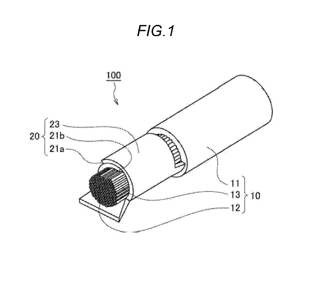
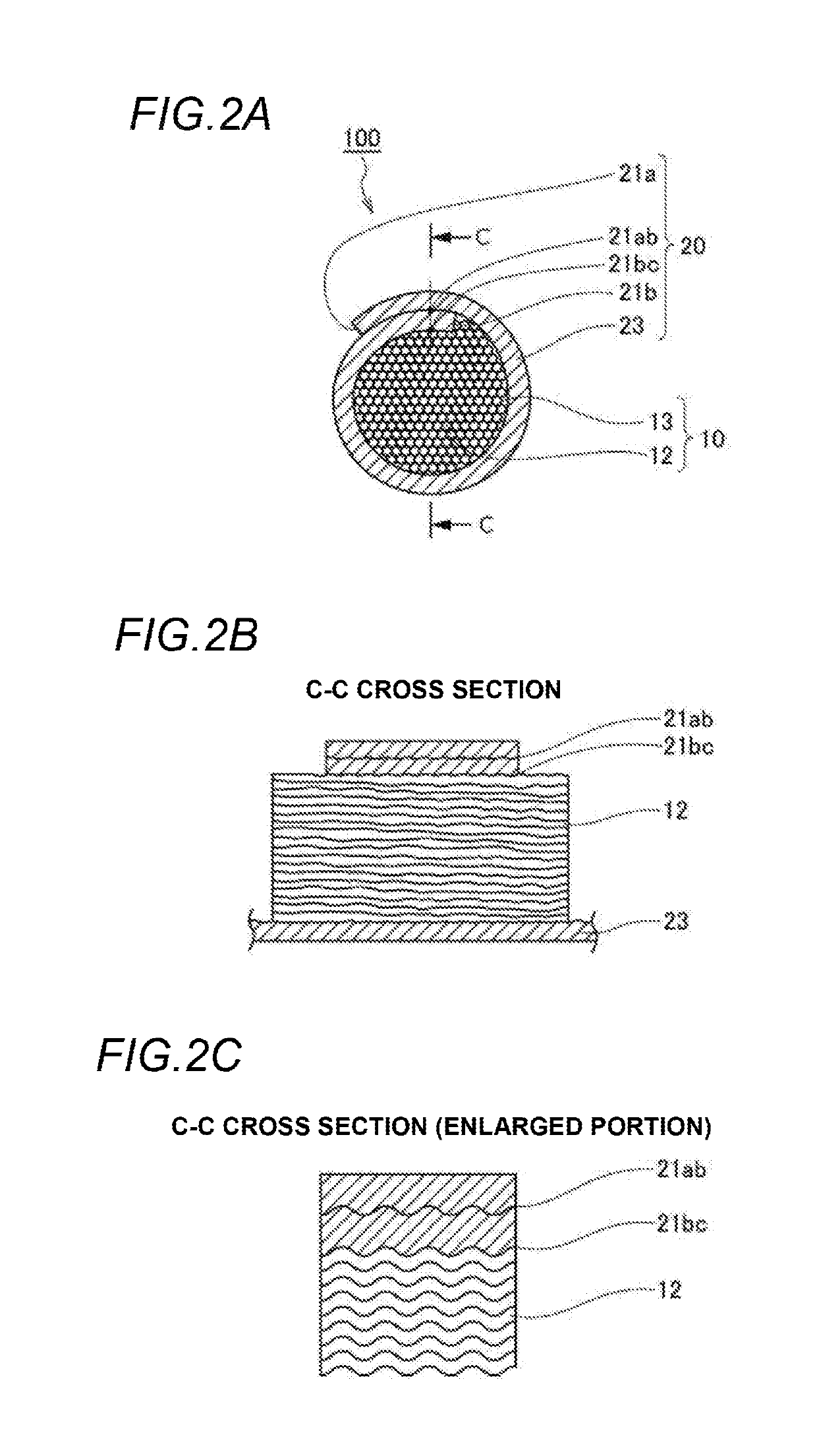
[0030]FIG. 1 and FIGS. 2A to 2C schematically illustrate the electromagnetic crimp terminal according to a first embodiment, in which FIG. 1 is a partial perspective view, FIG. 2A is a cross sectional view of a part of a front view, FIG. 2B is a cross sectional view of a part of side view, and FIG. 2C is an enlarged cross sectional view of the side view showing a part of FIG. 2B.

[0031]In FIG. 1 and FIGS. 2A to 2C, an electromagnetic crimp terminal 100 includes: an electric wire 10 including a conductor portion 12 whose periphery is covered with an insulation portion 11; and a terminal plate 20 including a crimped portion 23. The crimped portion 23 is electromagnetically crimped (electromagnetic crimping will be described separately in detail) onto a range (hereinafter referred to as “exposed portion”) 13 where a part of the insulation portion 11 is peeled off and the conductor portion 12 is exposed.

[0032]In the crimped portion 23, a plate-shaped portion...

second embodiment

Method for Manufacturing Electromagnetic Crimp Terminal

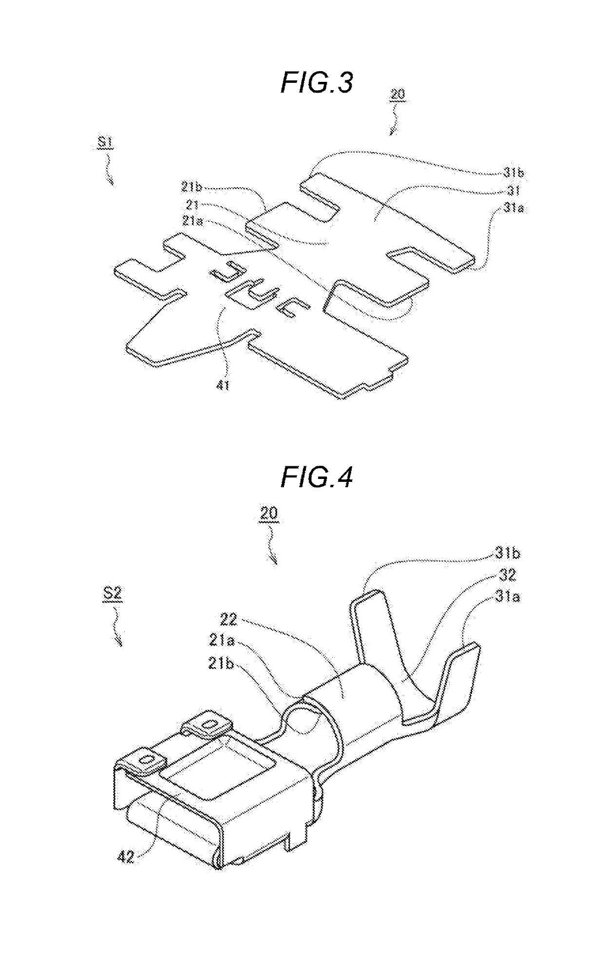
[0036]FIG. 3 to FIG. 9 schematically illustrate a method for manufacturing an electromagnetic crimp terminal according to a second embodiment, in which FIG. 3 is a perspective view of a step (S1) of forming the terminal plate, FIG. 4 is perspective view of a step (S2) of pressing, bending and forming a part of the terminal plate, FIG. 5 is a front view showing a part of FIG. 4, FIG. 6 and FIG. 7 are respectively perspective views during performing and of after completing a step (S3) of inserting a part of the electric wire into a part of the bent and formed terminal plate, FIG. 8 is a perspective view of a partial cross section of a step (S4) of inserting a part of the terminal plate into a discharge coil, and FIG. 9 is a cross sectional view of a front view of a step (S5) of instantaneously flowing a discharge current.

[0037]In FIG. 3 to FIG. 9, the method for manufacturing an electromagnetic crimp terminal is to manufacture the...

first modification

[0049]In FIG. 10, in the cylindrical portion 22, the one side edge 21a disposed on the outer side (precisely, the angle portion between the one side edge 21a and the inner surface) is brought into contact the outer surface slightly away from the other side edge 21b disposed on the inner side, and the other side edge 21b (precisely, an angle portion between the other side edge 21b and the outer surface) is brought into contact with the inner surface slightly away from the one side edge 21a. That is, since the one side edge 21a and the other side edge 21b contact with each other at two positions in the circumferential direction to increase the contact area, the electric resistance with respect to the induced current i2 is lowered, and as a result, the electromagnetic force F is increased. The contact in an axial direction of the electromagnetic crimp terminal 100 may be a continuous linear shape or an intermittent linear or dot shape.


PUM

PropertyMeasurementUnit
diameteraaaaaaaaaa
magnetic fieldaaaaaaaaaa
discharge currentaaaaaaaaaa

Abstract

An electromagnetic crimp terminal includes an electric wire and a terminal plate. The electric wire includes a conductor portion, an insulation portion which covers the conductor portion, and an exposed portion which is a part of the conductor portion exposed from the insulation portion. The terminal plate includes a crimped portion. The crimped portion is crimped onto the exposed portion. The crimped portion includes a first side edge and a second side edge. A vicinity of the first side edge and a vicinity of the second side edge overlap each other.

Description

CROSS-REFERENCE TO RELATED APPLICATIONS[0001]This application is based on and claims priority under 35 USC 119 from Japanese Patent Application No. 2018-076927 filed on Apr. 12, 2018, the contents of which are incorporated herein by reference.TECHNICAL FIELD[0002]The present disclosure relates to an electromagnetic crimp terminal, a manufacturing method of the electromagnetic crimp terminal, and a connecting terminal. Moreover present disclosure relates to an electromagnetic crimp terminal whose terminal is electromagnetically crimped onto a terminal plate, a manufacturing method of the electromagnetic crimp terminal, and a connecting terminal having a press-formed terminal plate.BACKGROUND ART[0003]In the related art, a terminal plate is crimped onto an end portion of an electric wire of a connecting terminal for transmitting a power supply current and an electric signal. Such crimping is known as crimping by mechanical caulking or crimping by metallurgical welding. In the crimping...

Claims


Application Information

Patent Timeline
Patent Type & Authority Applications(United States)
IPC IPC(8): H01R43/048H01R4/18
CPCH01R43/048H01R4/183H01R4/18H01R4/20H01R13/02H01R43/16H01R43/24B21D26/14B21D41/04B21D35/002B23K20/06B23K20/22B23K20/24B23K2101/32B23K2101/38
Inventor KOSHIISHI, MAKOTO
Owner YAZAKI CORP
Why Eureka
Try Eureka