
Capacitive sensor and capacitive sensor head

a capacitive sensor and capacitive sensor technology, applied in the direction of resistance/reactance/impedence, pulse technique, instruments, etc., can solve the problem of not being allowed, and achieve the effect of reducing the effect of external electromagnetic noise and simple configuration

Inactive Publication Date: 2019-10-24
SIMPLEX QUANTUM
View PDF2 Cites 3 Cited by
  • Summary
  • Abstract
  • Description
  • Claims
  • Application Information

AI Technical Summary

Benefits of technology

This patent is about a new capacitive sensor and sensor head that is designed to be resistant to external electromagnetic noise and the environment it is placed in. The goal is to make the sensor more accurate and reliable. This is done by using a simple configuration that reduces the impact of external influences and ensures accurate measurement.

Problems solved by technology

However, given that filter units for anti-noise measures as described above must be installed to all the capacitance detection devices when many capacitance detection devices are attempted to be installed for, for example, detecting approach of human body, it is highly possible that it is not permitted for a reason of an installation cost.

Method used


Image

  • Capacitive sensor and capacitive sensor head
  • Capacitive sensor and capacitive sensor head
  • Capacitive sensor and capacitive sensor head

Examples


second embodiment

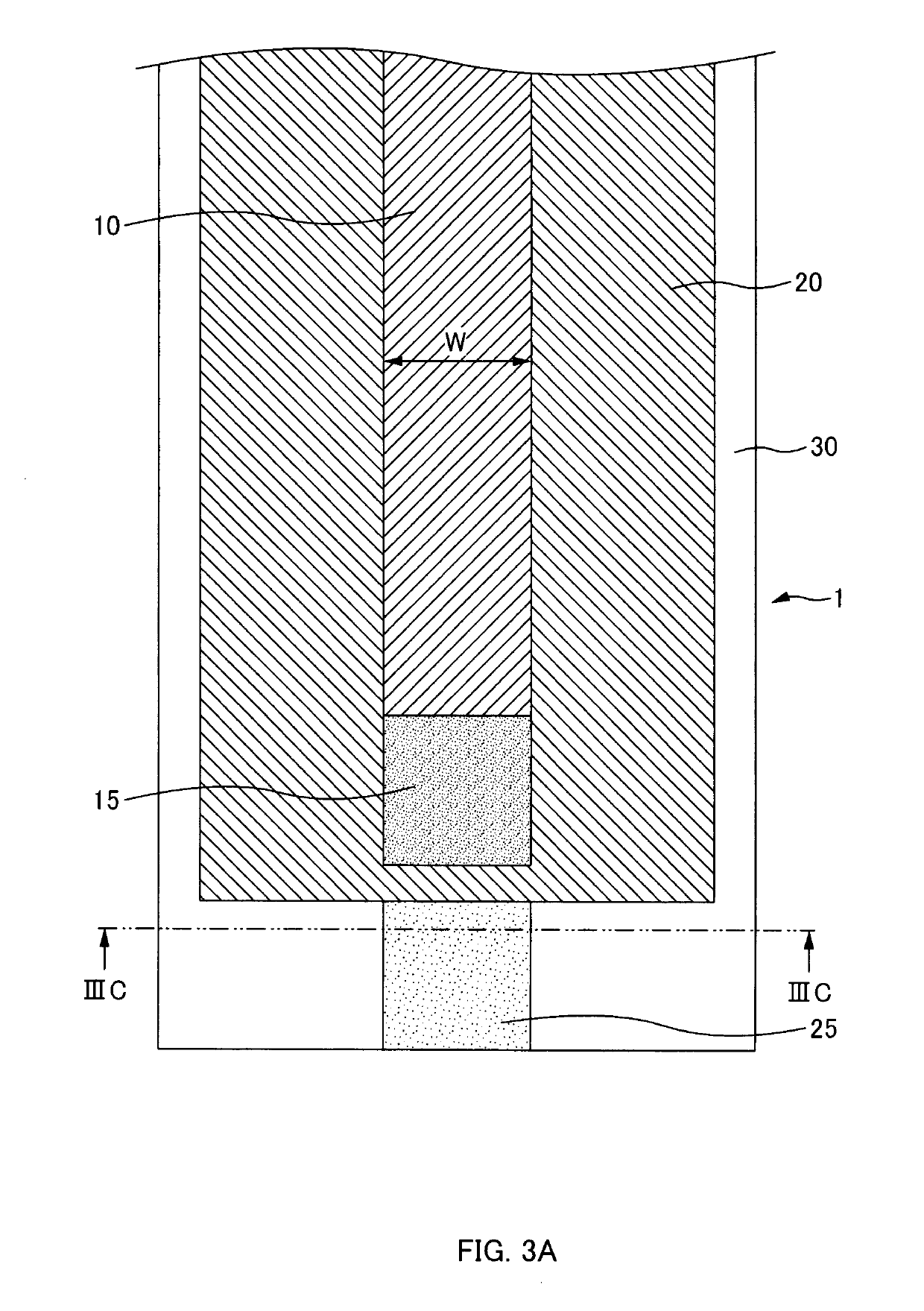
[0047]Next, another embodiment of the sensor head 1 used in the capacitive sensor 100 of the embodiment will be described with reference to the drawings. FIG. 4A to FIG. 4C illustrate an exemplary configuration of the sensor head 1 according to the present disclosure. FIG. 4A is a plan view of the sensor head 1, FIG. 4B is a bottom view of the sensor head 1, and FIG. 4C is a cross-sectional view of the sensor head 1. Note that a component identical or equivalent to that in the prior embodiment has an identical reference numeral attached in the following drawings.

[0048]In this embodiment, a configuration including the measuring electrode 10, the guard electrode 20, and the base material 30 is similar to that of a first embodiment described before. However, in this embodiment, while the guard electrode 20 is one, which is identical to the first embodiment, there are disposed two measuring electrodes 10 with a width smaller than that of the first embodiment. The measuring electrodes 10...

third embodiment

[0049]Next, yet another embodiment of the sensor head 1 used in the capacitive sensor 100 of the embodiment will be described with reference to the drawings. FIG. 5A to FIG. 5C illustrate an exemplary configuration of the sensor head 1 according to the present disclosure. FIG. 5A is a plan view of the sensor head 1, FIG. 5B is a bottom view of the sensor head 1, and FIG. 5C is a cross-sectional view of the sensor head 1.

[0050]In this embodiment, a configuration including the measuring electrode 10, the guard electrode 20, and the base material 30 is similar to that of the first embodiment and the second embodiment described before. However, this embodiment is different from the first and second embodiments in that three measuring electrodes 10 and three guard electrodes 20 are disposed. Each of the measuring electrodes 10 and the guard electrodes 20 is disposed on a top surface and a rear surface of the base material 30 such that centers in their width directions are aligned. Betwee...


PUM


Abstract

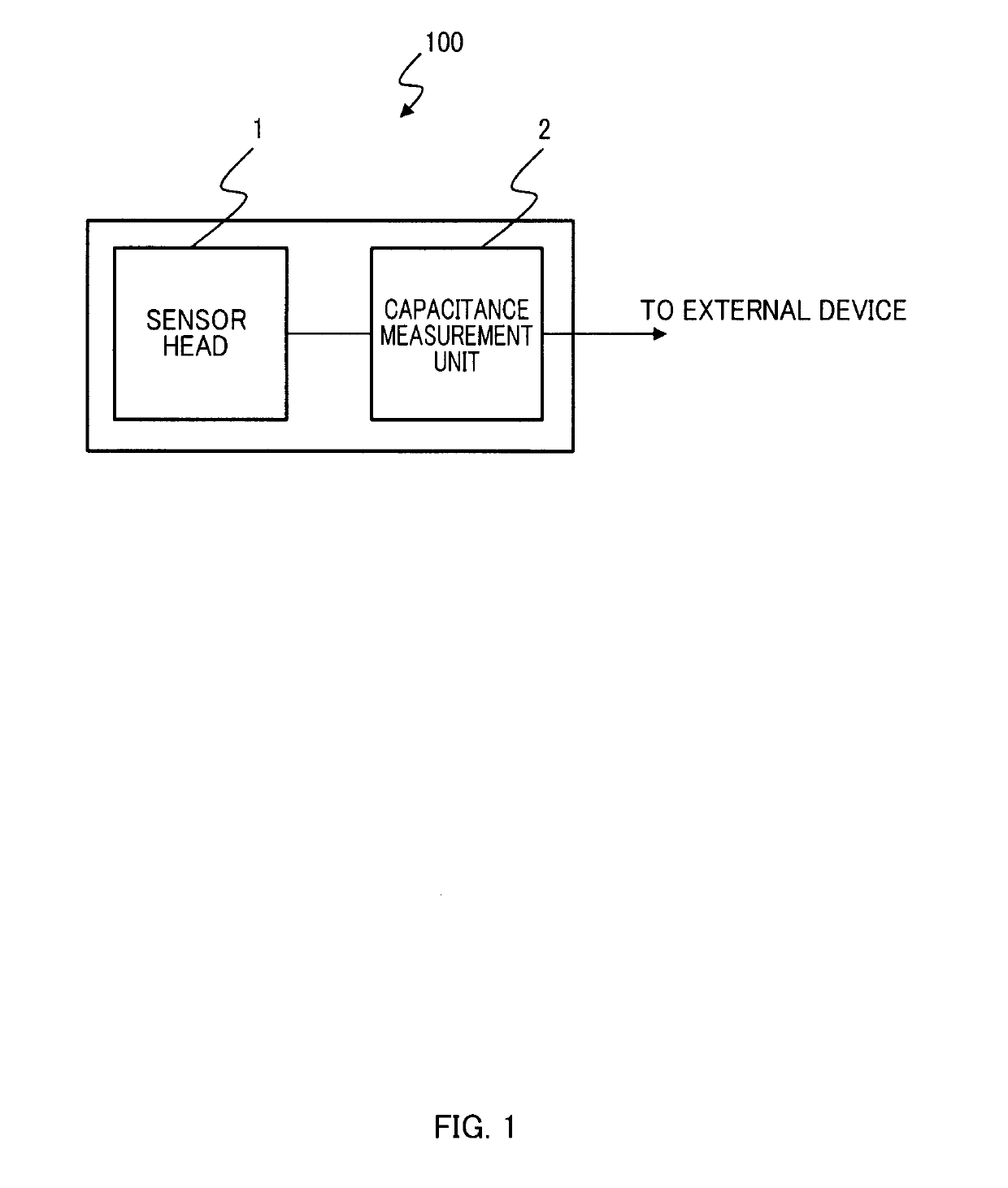
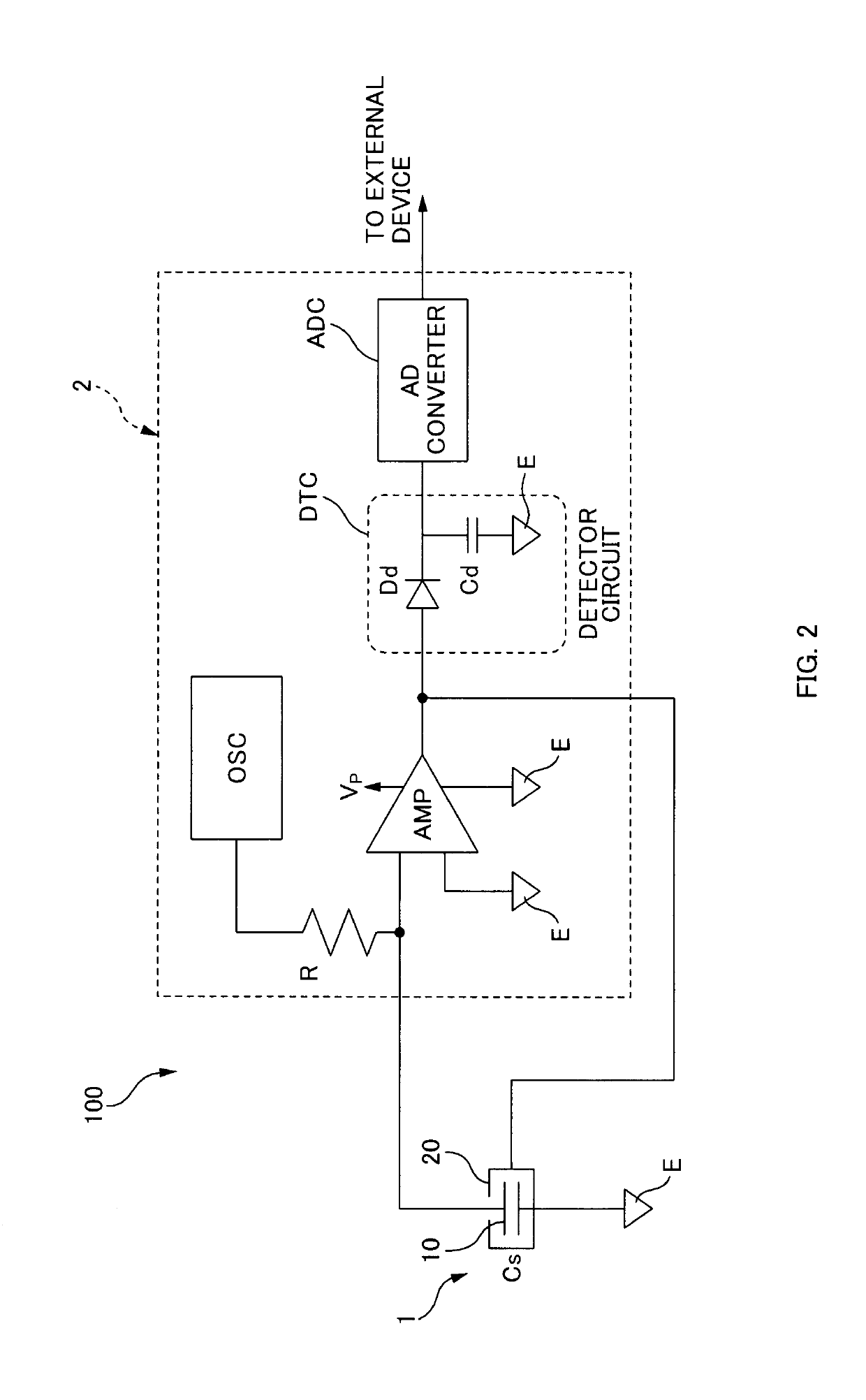
A capacitive sensor includes a sensor head, and a capacitance measurement unit. The sensor head includes a sheet-shaped base material, a measuring electrode on one surface of the base material, and a guard electrode on another surface of the base material. The guard electrode is positioned opposing to the measuring electrode in alignment with the same. The guard electrode has an outer periphery at least partially larger than an outer periphery of a shape formed by the measuring electrode. The capacitance measurement unit supplies an input voltage signal having a predetermined cycle to the measuring electrode, converts an output current signal output therefrom corresponding to the input voltage signal into an output voltage to output the output voltage as an output voltage signal, while supplying a voltage signal having a phase identical to a phase of the input voltage signal.

Description

CROSS-REFERENCE TO RELATED APPLICATION[0001]This application claims priority pursuant to 35 U.S.C. § 119 from Japanese Patent Application No. 2018-80531, filed on Apr. 19, 2018 of which is incorporated herein by reference.BACKGROUNDTechnical Field[0002]The present disclosure relates to a capacitive sensor and a capacitive sensor head.Related Art[0003]A capacitive sensor is used for, for example, a touchscreen for inputting information and a sensor for proximity detection of various objects. As is commonly known, by measuring a capacitance between a measuring electrode and a ground or between a pair of measuring electrodes, and detecting a change of the measurement value, the capacitive sensor ensures detecting a contact or an approach of various objects, such as a human body, to the measuring electrode.[0004]For example, Japanese Unexamined Patent Application Publication No. 2017-142270 discloses a capacitance detection device that uses a sensor sheet including a sheet-shaped dielec...

Claims


Application Information

Patent Timeline
IPC IPC(8): G01R27/26G01D5/24
CPCG01R27/2605G01D5/24H03K17/962H03K2217/960705H03K2217/96071H03K2217/960765
Inventor MIKAMI, YOSHIHIRO
Owner SIMPLEX QUANTUM
Learn More