System for high-temperature tight coupling of a stack having soec/sofc-type solid oxides

a technology of solid oxide and high-temperature tight coupling, which is applied in the field of high-temperature electrolysis (hte) of water, can solve the problems of reducing yield, damage to the stack, and loss of yield

Active Publication Date: 2019-10-24
COMMISSARIAT A LENERGIE ATOMIQUE ET AUX ENERGIES ALTERNATIVES
View PDF0 Cites 3 Cited by
  • Summary
  • Abstract
  • Description
  • Claims
  • Application Information

AI Technical Summary

Problems solved by technology

Moreover, a seal must be obtained between the anode and cathode compartments, without which the gases produced will recombine, resulting in a reduced yield and above all in the appearance of hot spots, which damage the stack.
Finally, a good distribution of the gases is required, both at the inlet and on collection of the gases produced, without which distribution there will be a loss of yield, non-uniformity of pressure and non-uniformity of temperature within the different individual cells, or even unacceptable deterioration of the electrochemical cells.
However, the major drawback thereof is its lack of resistance to high temperatures, whereby the rear ferrule, the front ferrule and the pipe can become welded together by diffusion bonding, preventing the junction from being disassembled.
However, this solution is not suitable at high temperatures, the operation whereof only allows for a maximum temperature of about 537° C.
However, the welding operations on a stack 20 mounted in a furnace 10 are very complicated as a result of the reduced accessibility for welding the pipes around the perimeter.
These bushings thus allow for the passage of elements without any discontinuity, and do not allow for a sealed junction to be made between two elements.
The couplings of the gas supply and discharge devices at the cold parts PF of the furnace 10 co...

Method used


Image

  • System for high-temperature tight coupling of a stack having soec/sofc-type solid oxides
  • System for high-temperature tight coupling of a stack having soec/sofc-type solid oxides
  • System for high-temperature tight coupling of a stack having soec/sofc-type solid oxides

Examples


Embodiment Construction

[0048]The purpose of the invention is to at least partially satisfy the aforementioned needs and overcome the drawbacks regarding the productions of the prior art.

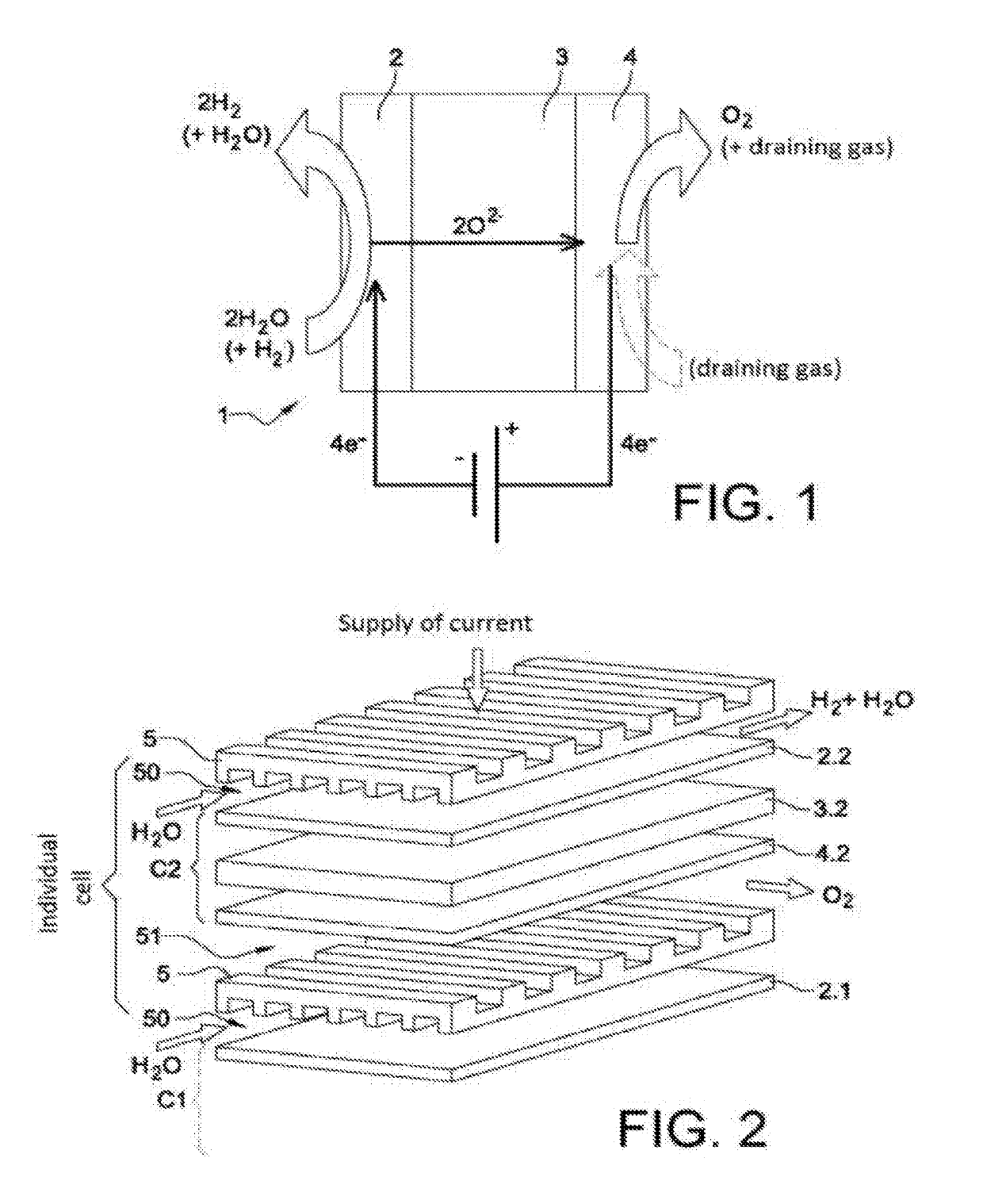
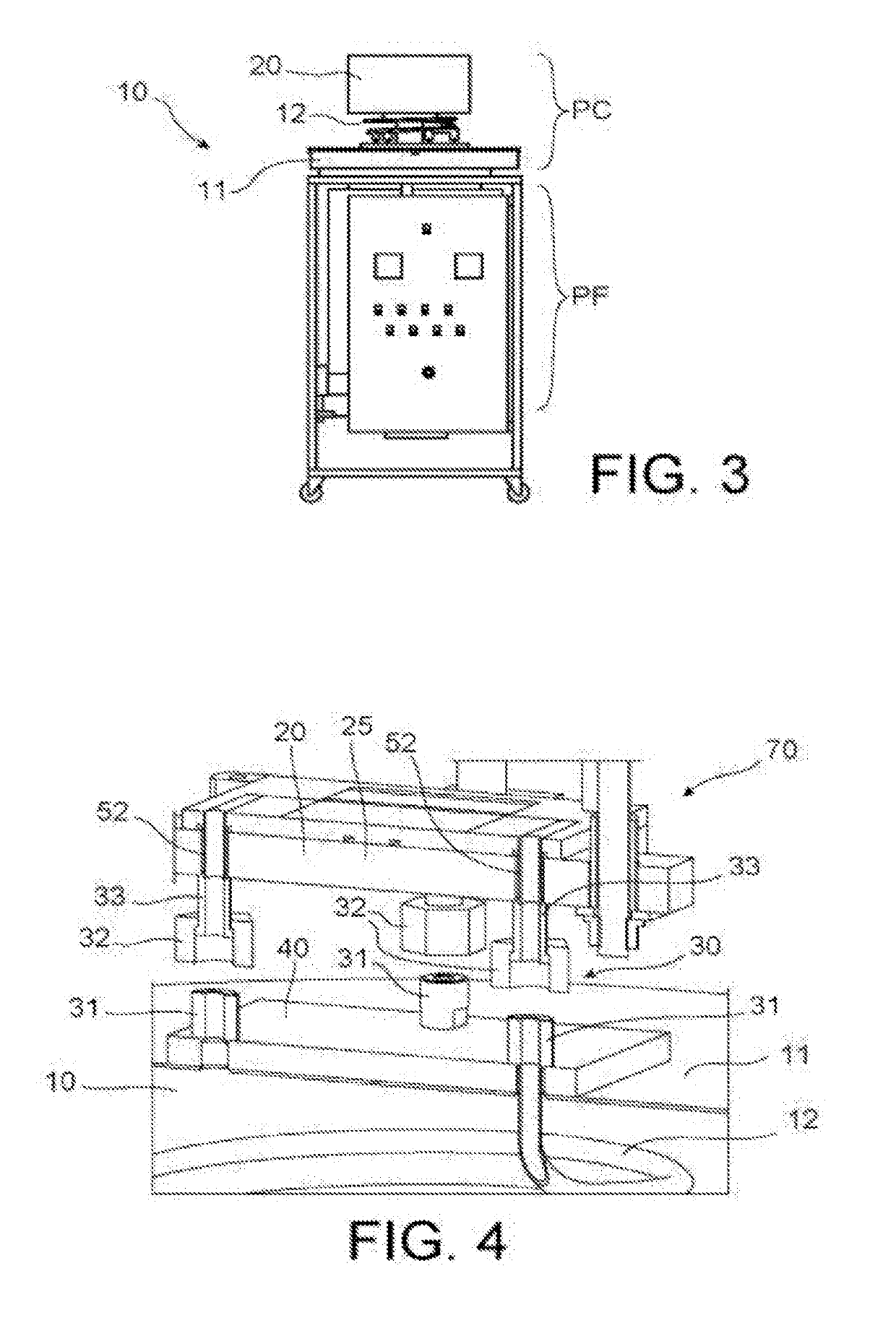
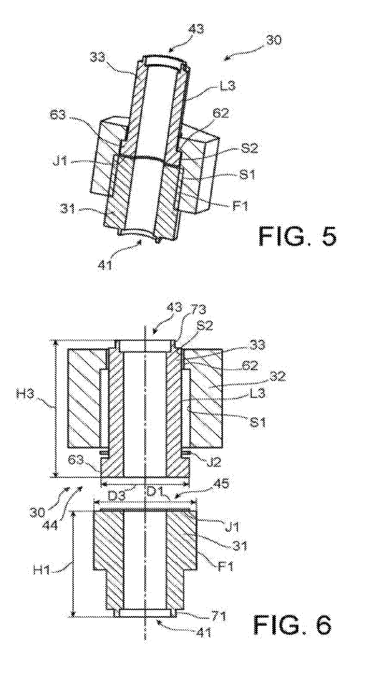
[0049]It in particular relates to the production of a particular design of the coupling of a high-temperature electrolysis (SOEC) or fuel cell (SOFC) stack, and more specifically to the production, in the hot part, i.e. inside the enclosure of a furnace, and perpendicular to the gas inlets and outlets, high-temperature sealed connections, for example able to withstand temperatures of up to about 900° C., that can be removed and reused, thus giving the stack a “Plug & Play”-type feature. The invention, according to one of the aspects thereof, thus relates to a system for the high-temperature sealed coupling of a stack having SOEC / SOFC-type solid oxides, characterised in that it comprises:[0050]a hollow connector that is at least partially threaded on the outer surface thereof, referred to as a threaded connector, intended t...


PUM


Abstract

A coupling system for high-temperature tight coupling of a stack having SOEC/SOFC-type solid oxides is described. The system includes a threaded hollow connector, a smooth hollow connector, and a threaded nut. The threaded hollow connector includes an opening for establishing fluid communication with a gas inlet/outlet pipe and is intended to be attached to the gas inlet/outlet pipe. The smooth hollow connector includes an opening for establishing fluid communication with a gas inlet/outlet pipe of the stack and is intended to be attached to the inlet/outlet pipe. The threaded nut engages with the threaded hollow connector to form a screw/nut system, slides relative to the smooth hollow connector, and includes a first threaded portion and a second smooth portion in sliding contact with the smooth hollow connector.

Description

TECHNICAL FIELD[0001]The present invention relates to the general field of high-temperature electrolysis (HTE) of water, in particular high-temperature steam electrolysis (HTSE), carbon dioxide (CO2) electrolysis, or even high-temperature co-electrolysis (HTE) of water with carbon dioxide (CO2).[0002]More specifically, the invention relates to the field of high-temperature solid oxide electrolysers, commonly denoted by the acronym SOEC (Solid Oxide Electrolyser Cell).[0003]It also relates to the field of high-temperature solid oxide fuel cells, commonly denoted by the acronym SOFC (Solid Oxide Fuel Cell).[0004]Thus, more generally speaking, the invention relates to the field of solid oxide stacks of the SOEC / SOFC type operating at a high temperature.[0005]More specifically, the invention relates to a system for the high-temperature sealed coupling of a stack having SOEC / SOFC-type solid oxides, in addition to an assembly comprising a stack having SOEC / SOFC-type solid oxides and a fur...

Claims


Application Information

Patent Timeline
IPC IPC(8): H01M8/248C25B1/04C25B9/20C25B9/04H01M8/0271H01M8/1246H01M8/04014H01M8/2428
CPCH01M8/0271C25B1/04C25B9/04C25B9/20H01M8/2428H01M8/248H01M8/04022H01M8/1246H01M2008/1293C25B15/08H01M8/2483H01M8/2432H01M8/04037Y02E60/50Y02E60/36C25B9/73C25B9/75C25B11/036C25B9/65
Inventor PLANQUE, MICHELORESIC, BRUNOROUX, GUILHEMBERNARD, CHARLOTTESZYNAL, PHILIPPE
Owner COMMISSARIAT A LENERGIE ATOMIQUE ET AUX ENERGIES ALTERNATIVES
Why Eureka
Try Eureka