Multifunctional snow blocking device connecting assembly and mounting method

A connection component and multi-functional technology, which is applied in the field of connection components and installation of multi-functional snow protection devices, can solve the problems of long installation time, large safety hazards, and affecting the normal use of snow protection devices, and achieve the effect of shortening the installation time

Active Publication Date: 2022-05-17
江苏伯尔特新型材料有限公司
View PDF26 Cites 0 Cited by
  • Summary
  • Abstract
  • Description
  • Claims
  • Application Information

AI Technical Summary

Problems solved by technology

[0002] Rainy and snowy weather is a common occurrence in winter. Heavy snow covers the roof. After the ice is on, due to the influence of the inclination of the roof construction, it is easy to slide along the roof as a whole, and it is easy to hurt passers-by. There is a big safety hazard. In order not to affect the load-bearing of the roof and to prevent a large area of ​​snow from sliding down and hurting passers-by, the existing technology uses a snow-blocking device as a blocker to prevent the snow from sliding down, but the installation uses a large number of bolts and fasteners to fasten the overall structure, and the construction volume It takes a long time to install, and the installation stability of the connection components of the existing snow protection device is poor, and it is easy to dump, which affects the normal use of the snow protection device. Therefore, a multifunctional snow protection device connection component and installation are designed here. method to solve the above problems

Method used


Image

  • Multifunctional snow blocking device connecting assembly and mounting method
  • Multifunctional snow blocking device connecting assembly and mounting method
  • Multifunctional snow blocking device connecting assembly and mounting method

Examples


Embodiment 1

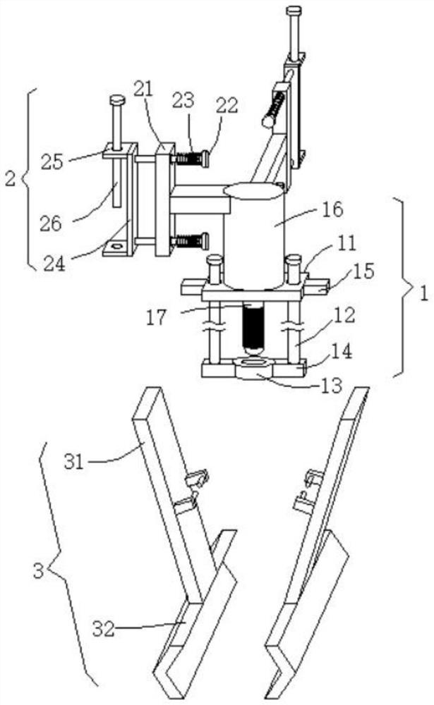
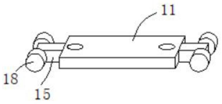
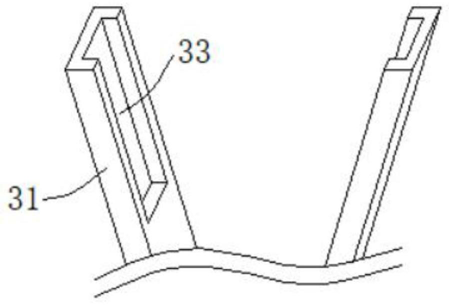
[0018] Embodiment one please refer to figure 1 , Figure 4 and Figure 5 , the present embodiment provides a multifunctional snow shielding device connection assembly and installation method, the connection assembly includes an adjustment mechanism 1, a clamping mechanism 3 and a docking mechanism 2, the adjustment mechanism 1 includes a top plate 11 and a socket 13, the top plate 11 The bottom end is vertically fixed with a push rod 17, and the socket 13 is provided with a positioning hole for plugging in with the push rod 17. The clamping mechanism 3 includes two guide hinge plates 31, and the outer wall of the socket 13 is symmetrically fixed with a support block 14. , the two guide hinge plates 31 are symmetrically distributed around the socket 13, and are hinged with the corresponding support block 14, and both ends of the top plate 11 are fixedly provided with a pressure block 15 capable of pressing down the guide hinge plate 31, the pressure block 15 Pressing down can...

Embodiment 2

[0024] Embodiment 2 Please refer to Figure 6 , On the basis of Embodiment 1, a further improvement is made: 6. The top of the support column 16 is provided with a strengthening mechanism 4, which can further strengthen the connection through the strengthening mechanism 4. The strengthening mechanism 4 includes a threaded connecting rod 41, a threaded sleeve 42 and two pull rods 43, the top of the support column 16 is provided with a plug-in slot 19, the bottom end of the threaded connecting rod 41 is inserted into the plug-in slot 19, and the outer wall of the thread is hinged, and the other end of the pull rod 43 is hinged with a clamping plate 44, and the clamping plate 44 The side wall is provided with a clamping gap. When the V-shaped splint 32 is clamped on both sides of the upwardly protruding reinforcing ribs formed by the roll forming of the color steel tile, the bottom end of the threaded connecting rod 41 is inserted into the insertion groove 19, and then The thread...

Embodiment 3

[0025] Embodiment 3 The buffer tank 111 has a "middle" shape structure, and the outer wall of the positioning rod 112 is fixedly sleeved with a limit plate 113 located inside the buffer tank 111. By setting the limit plate 113, on the one hand, it does not affect the position of the positioning rod 112. The inside of the buffer groove 111 slides, on the other hand, it can prevent the positioning rod 112 from being pulled out from the inside of the buffer groove 111 to affect the positioning of the push rod 17 .

[0026] The upper end of the support block 14 is vertically fixed with a T-shaped guide rod 12, and the top plate 11 is provided with an insertion hole for sliding insertion with the T-shaped guide rod 12. Stability when briquetting block 15 is pressed down.

[0027] The end of briquetting block 15 rotates and is provided with roller 18, and the upper end of guide hinge plate 31 sidewall is provided with the rolling groove 33 that is engaged with roller 18 rolling enga...


PUM


Abstract

The invention discloses a multifunctional snow blocking device connecting assembly and a mounting method, and relates to the technical field of snow blocking, the connecting assembly comprises an adjusting mechanism, a clamping mechanism and a butt joint mechanism, the adjusting mechanism comprises a top plate and a bayonet socket, a top rod is vertically fixed to the bottom end of the top plate, and the clamping mechanism comprises two guide hinge plates; the two guide hinge plates are hinged to the corresponding supporting blocks, V-shaped clamping plates are fixedly arranged at the bottom ends of the guide hinge plates, a supporting column is fixedly arranged at the top end of the top plate, and the butt joint mechanism is arranged on one side of the top end of the outer wall of the supporting column. The two V-shaped clamping plates of the clamping mechanism are stably clamped on the two sides of the reinforcing rib which is formed by rolling the color steel tile and protrudes upwards, the two ends of the snow blocking rod of the snow blocking device are connected with the butt joint mechanisms of the two adjacent connecting assemblies, a large number of bolt fasteners do not need to be consumed, the installation time is shortened, and the installation efficiency is improved. It is ensured that the whole connecting assembly is stably installed on the roof color steel tile, and the snow blocking device can effectively prevent a large amount of accumulated snow from sliding down along the color steel tile for a long time.

Description

technical field [0001] The invention relates to the technical field of snow shielding devices, in particular to a multifunctional snow shielding device connection assembly and an installation method. Background technique [0002] Rainy and snowy weather is a common occurrence in winter. Heavy snow covers the roof. After the ice is on, due to the influence of the inclination of the roof construction, it is easy to slide along the roof as a whole, and it is easy to hurt passers-by. There is a big safety hazard. In order not to affect the load-bearing of the roof and to prevent a large area of ​​snow from sliding down and hurting passers-by, the existing technology uses a snow-blocking device as a blocker to prevent the snow from sliding down, but the installation uses a large number of bolts and fasteners to fasten the overall structure, and the construction volume It takes a long time to install, and the installation stability of the connection components of the existing snow...

Claims


Application Information

Patent Timeline
Patent Type & Authority Applications(China)
IPC IPC(8): E04D13/10
CPCE04D13/10Y02E10/50
Inventor 朱森林刘新博孙凌云
Owner 江苏伯尔特新型材料有限公司
Why Eureka
Try Eureka