Internal fixator for bone fracture

a bone fracture and fixator technology, applied in the field of internal fixators, can solve the problems of internal bone fracture fracture, etc., and achieve the effect of reducing the risk of the femoral head being torn apart by the inner fixing member

Active Publication Date: 2019-11-07
BFN RES KK
View PDF3 Cites 5 Cited by
  • Summary
  • Abstract
  • Description
  • Claims
  • Application Information

AI Technical Summary

Benefits of technology

[0030]According to the bone fracture internal fixator for repairing a femoral neck fracture of the present invention, the load from the pelvis can be supported in an evenly distributed manner Also, by at least partly thickening the inner fixing member (lag screw etc.), the connection between the inner fixing member and the femur can be strengthened, and the risk of the femoral head being torn apart by the inner fixing member can be reduced.

Problems solved by technology

However, such an internal fixator 101 has the following problems.

Method used


Image

  • Internal fixator for bone fracture
  • Internal fixator for bone fracture
  • Internal fixator for bone fracture

Examples


first embodiment

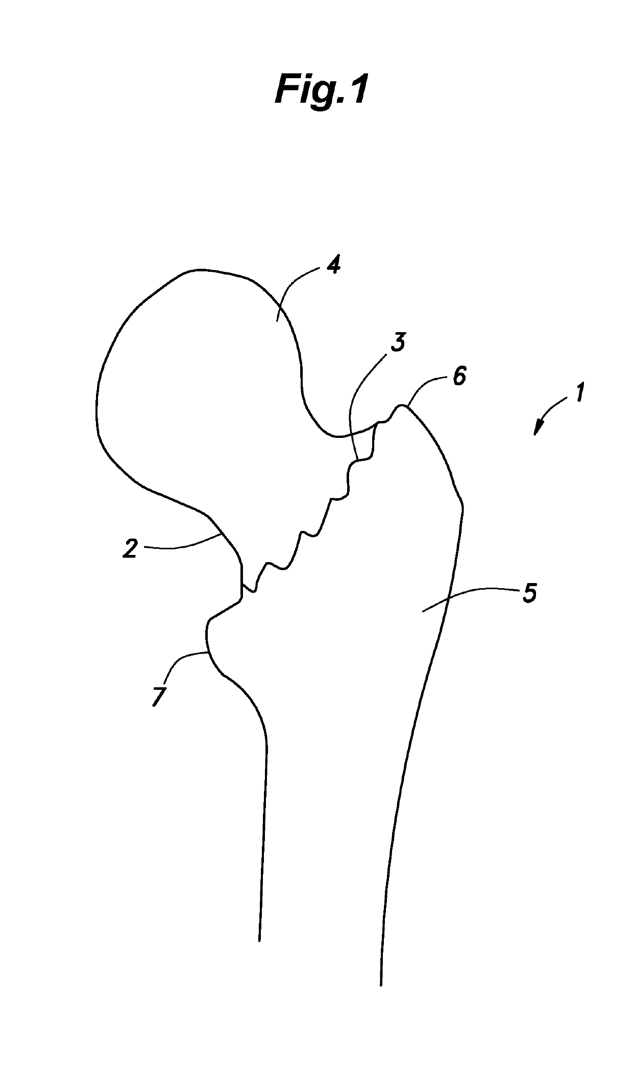
[0050]FIGS. 9 and 10 show a bone fracture internal fixator 10 for repairing a femoral neck fracture according to a first embodiment. The bone fracture internal fixator 10 includes an intramedullary nail 11 configured to be placed in the medullary cavity of a femoral shaft 5, and a rod-shaped inner fixing member 12 configured to be connected between a femoral head 4 and the femoral shaft 5.

[0051]As shown in (A) of FIG. 11, the intramedullary nail 11 is formed with a through hole 13 through which the inner fixing member 12 may be passed, and the central axial line 13a of the through hole 13 is laterally offset from the central axial line 11a of the intramedullary nail 11. The through hole 13 is formed in a widened portion 14 of the intramedullary nail 11, and the width of the widened portion 14 as measured in a direction orthogonal to the extending direction of the through hole 13 is greater than the widths of the parts of the intramedullary nail 11 above and below the widened portion...

second embodiment

[0058](A) of FIG. 12 shows a bone fracture internal fixator 30 according to a second embodiment. Similarly to the first embodiment, the bone fracture internal fixator 30 includes an intramedullary nail 31 configured to be placed in the medullary cavity of the femoral shaft 5, and a rod-like inner fixing member 32 configured to be connected between the femoral head 4 and the femoral shaft 5. In particular, the structure of the inner fixing member 32 differs from that of the inner fixing member 12 of the first embodiment. The parts corresponding to those of the first embodiment may be omitted in the following disclosure.

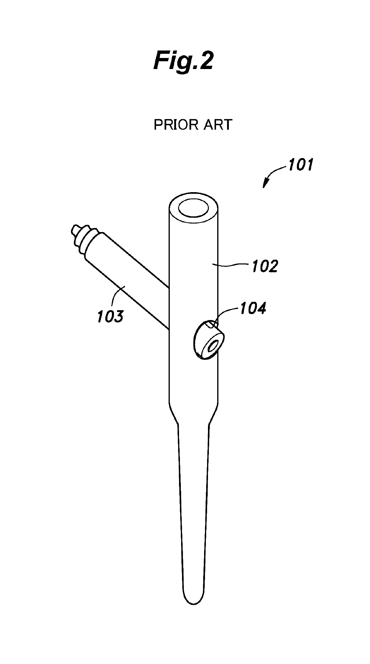
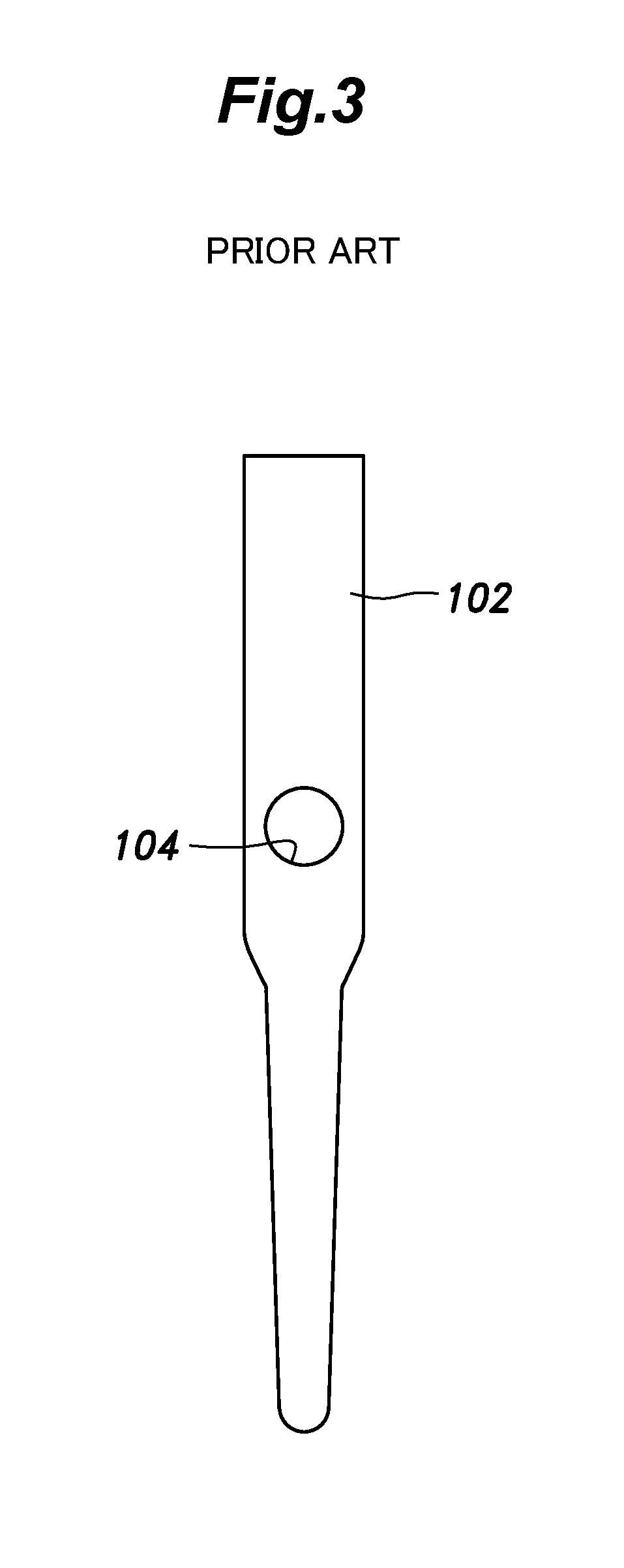
[0059]The intramedullary nail 31 is constructed in a similar manner as the conventional one. More specifically, the central axial line of the through hole 33 crosses the central axial line of the intramedullary nail 31, instead of being offset therefrom.

[0060]The inner fixing member 32 is a linearly extending, rod-like member, and includes a shaft portion34 configured ...

third embodiment

[0065]FIG. 13 shows a bone fracture internal fixator 40 according to a third embodiment. Similarly as in the first and second embodiments, the bone fracture internal fixator 40 includes an intramedullary nail 41 configured to be placed in the medullary cavity of the femoral shaft 5, and a linearly extending, rod-like inner fixing member 42 connecting the femoral head 4 and the femoral shaft 5 to each other. In the bone fracture internal fixator 40 according to the third embodiment, the diameter of the inner fixing member 42 is generally increased, and bone cement, an osteogenic agent, artificial bone or the like can be charged into a part where the inner fixing member 42 is connected to the femoral head 4.

[0066]As shown in FIG. 14, the intramedullary nail 41 is formed with a through hole 43 through which the inner fixing member 42 is to be inserted, and the through hole 43 is formed in a widened portion 44 formed in the intramedullary nail 41. In the widened portion 44, the width in...


PUM


Abstract

A bone fracture internal fixator for repairing a bone fracture of a femoral neck that allows load to be applied to the associated bone parts evenly, and increases the connecting strength between the femoral head and femoral shaft while minimizing the risk of the femoral head being torn apart by the inner connecting member by increasing the diameter of the inner fixing member. The central axial line of the femoral head is offset from the central axial line of the intramedullary nail placed in the medullary cavity of the femoral shaft. In order to bring the inner fixing member such as a lag screw configured to be inserted through the femoral neck close to the central axial line of the femoral neck, the central axial line of the through hole for receiving the inner fixing member is offset from the central axial line of the intramedullary nail.

Description

TECHNICAL FIELD[0001]The present disclosure relates to an internal fixator for stabilizing a bone fracture in the field of orthopedic surgery, and, in particular, to a bone fracture internal fixator for repairing a femoral neck fracture.BACKGROUND ART[0002]As shown in FIG. 1, a bone fracture 3 occurs to a femoral neck 2 that defines a boundary between a femoral head 4 and a femoral shaft 5. A greater trochanter 6 and a lesser trochanter 7 are located on the side of the femoral shaft 5. As shown in FIGS. 2 to 4, a conventional internal fixator 101 for repairing a femoral neck fracture includes an intramedullary nail 102 passed into a medullary cavity of a femoral shaft 5, and a lag screw 103 that connects a femoral head 4 to the femoral shaft 5 (see Patent Document 1, for example). The lag screw 103 is passed into a through hole 104 formed in the intramedullary nail 102 from the threaded front end thereof so that the front end thereof is fixed in the femoral head 4, and the rear end ...

Claims


Application Information

Patent Timeline
Patent Type & Authority Applications(United States)
IPC IPC(8): A61B17/74A61B17/72
CPCA61B17/748A61B17/7283A61B17/7233A61B17/744
Inventor TANAKA, SAKAEMATSUBARA, TAKEHIROYAMADA, IKUFUMI
Owner BFN RES KK
Why Eureka
Try Eureka