Automatic terminal fitting device for a four-pin electrical connector

a technology of automatic fitting and electrical connector, which is applied in the direction of coupling device connection, electrical apparatus, connections, etc., can solve the problems of low production efficiency, high labor investment, and high manpower consumption, and achieves improved accuracy of rubber shell conveying and positioning, and keeps the terminal strip running smoothly.

Active Publication Date: 2019-11-07
DONGGUAN UNIV OF TECH
View PDF0 Cites 12 Cited by
  • Summary
  • Abstract
  • Description
  • Claims
  • Application Information

AI Technical Summary

Benefits of technology

[0013]As a result of the structure of the conveying device, by rotating the screw shaft with the second motor, it is possible to move the positioning block, in the meantime, realize precise positioning with the three sets of photoelectric sensor together with the shading sheet, which improves accuracy of rubber shell conveying and positioning.
[0014]In addition, as a result of the terminal feeding device with a guide pulley, it is possible to keep the terminal strip going smoothly, and avoid jam due to vibration.
[0015]Similarly, as a result of the structure of the terminal assembly mechanism, the first cylinder pushes the first pushing plate forward to have the second rotating shaft slide along the upper gripping slot, driving the upper seat to move up and down in reciprocating motion; at the same time, by making the first rotating shaft slide along the lower gripping slot drives the lower seat to move up and down in reciprocating motion, which achieves both material gripping and terminal pushing sophisticatedly.
[0016]Still further,

Problems solved by technology

At present, electrical connector assembly is done manually or semi-automatically, which involves complex working procedures, and due to large amount of manual work, some problems such

Method used


Image

  • Automatic terminal fitting device for a four-pin electrical connector
  • Automatic terminal fitting device for a four-pin electrical connector
  • Automatic terminal fitting device for a four-pin electrical connector

Examples


Embodiment Construction

[0100]In order to enable a person skilled in the art to better understand the technical scheme of the present invention, the following description may be given to the present invention in detail with reference to the accompanying drawings. The description of the invention is merely exemplary and explanatory and should not limit the scope of the protection scope of the present invention.

[0101]As it shown in FIGS. 1-14, the structure of the invention is shown as follows:

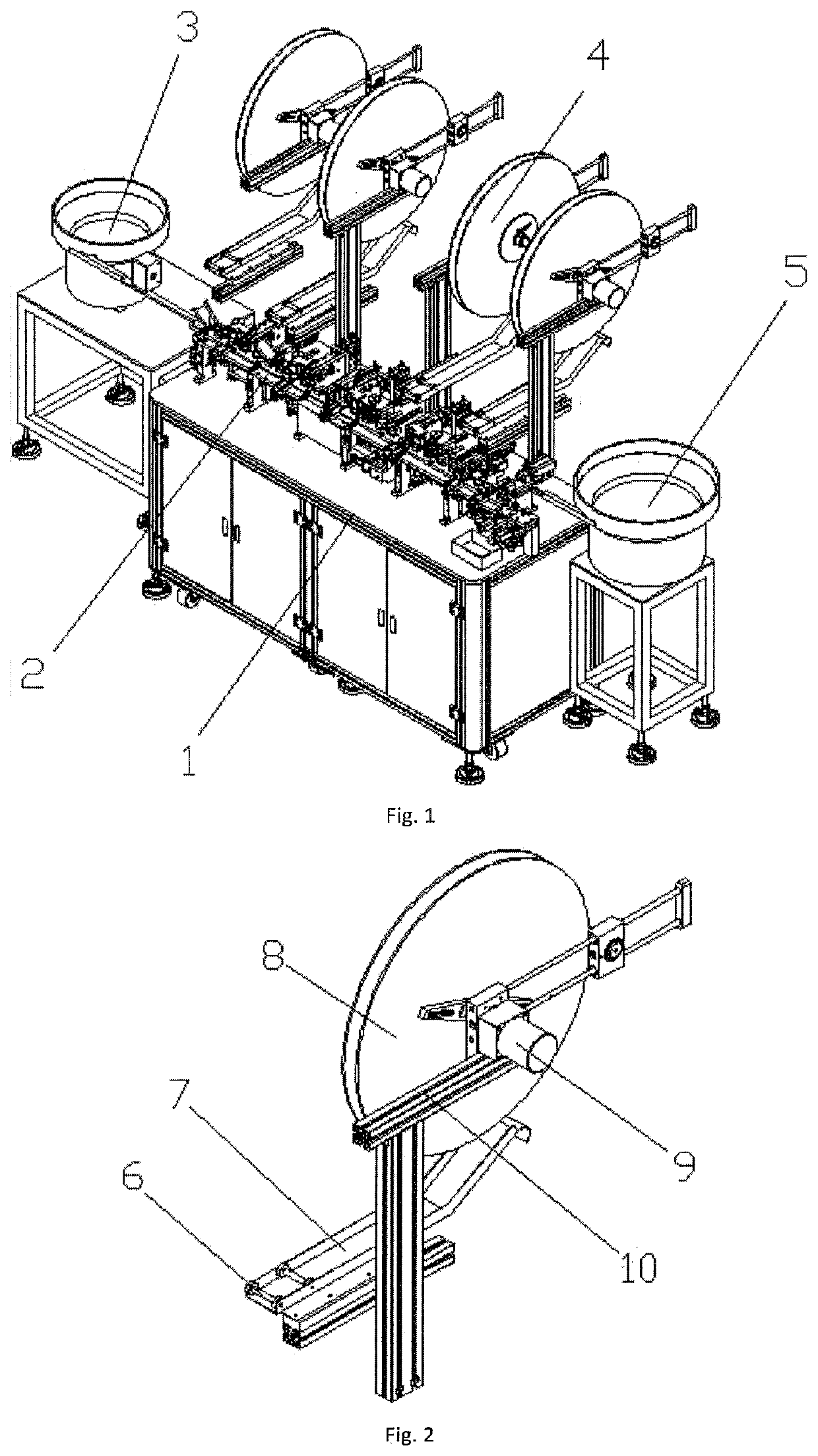
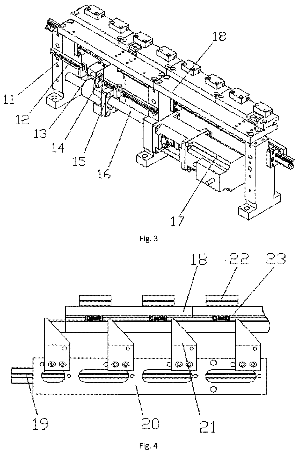
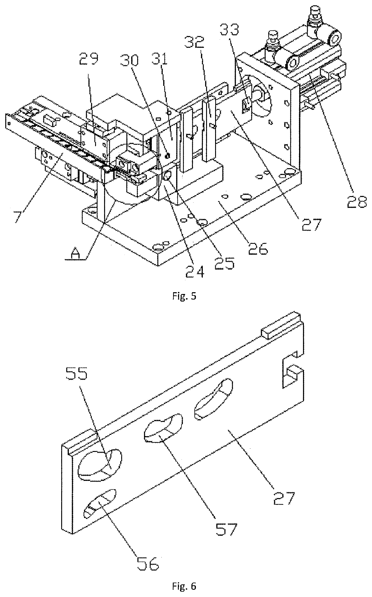
[0102]an automatic terminal fitting device for four-pin electrical connector comprises a rack 1, a power control box and a conveying device 2 which is provided on the rack 1; on the said rack 1, a rubber shell vibration disc 3, a terminal fitting mechanism, a back cover vibration disc 5 are provided along the transport direction; the rubber shell vibration disc 3 is connected to the front side of the conveying device 2 by a rubber shell transport rail; the terminal fitting mechanism 2 is provided on the back side of th...


PUM


Abstract

The present invention relates to an automatic terminal fitting device for four-pin electrical connector which may comprise a rack, power control box and conveying device provided on the rack. A rubber shell vibration disc, a terminal fitting mechanism, and a back cover vibration disc are provided on the rack along the transporting direction. The rubber shell vibration disc is connected to the front end of the conveying device by a rubber shell transportation rail. The terminal fitting mechanism is provided on the back side of the conveying device and engages with the terminal feeding device provided on the rack. The back cover vibration disc is provided on the back side of the conveying device, to the right side of the terminal fitting mechanism. And the terminal fitting mechanism may include four sets of terminal fitting devices sequentially provided on the back side of the conveying device. On the right side of the terminal fitting devices, a terminal strip bending device engaging with the conveying device is provided. The present invention effectively addresses the problems existing when fitting terminals manually during assembly, such as low production efficiency, high manpower consumption, intensive labor investment, relatively high potential safety hazard occurrence, and unsatisfactory connector defect rate.

Description

FIELD OF THE INVENTION[0001]The present invention relates to assembly technology of electrical connectors, and more especially discloses an automatic terminal fitting device for a four-pin electrical connector.BACKGROUND OF THE INVENTION[0002]Existing four-pin electrical connector product, generally comprise three main parts, namely, a rubber shell 23, a terminal 38, and a back cover 64, and in this regard, the correct assembly of the electrical connector components of the rubber shell 23, the terminal 38 and the back cover 64 according to their mutual relationship. At present, electrical connector assembly is done manually or semi-automatically, which involves complex working procedures, and due to large amount of manual work, some problems such as low production efficiency, high manpower consumption, intensive labor investment, relatively high safety hazard potentials and undesirable product deficiency rate etc. are detected.SUMMARY OF THE INVENTION[0003]The present invention rela...

Claims


Application Information

Patent Timeline
IPC IPC(8): H01R13/405
CPCH01R13/405H01R43/20
Inventor LI, CHUANBAI, YUN
Owner DONGGUAN UNIV OF TECH
Why Eureka
Try Eureka