
Thermal Insulating Material And Method

a technology of thermal insulation material and thermal insulation layer, which is applied in the direction of synthetic resin layered products, transportation and packaging, sleeping rug, etc., can solve the problems of increased airborne particles, body cannot replace fast enough, and patients are warm,

Active Publication Date: 2019-11-14
BLIZZARD PROTECTION SYST
View PDF6 Cites 1 Cited by
  • Summary
  • Abstract
  • Description
  • Claims
  • Application Information

AI Technical Summary

Benefits of technology

The present invention provides a thermal insulating material for patients in hospital settings to keep them warm and prevent hypothermia. The material is made up of layers of nonwoven textile or polymer laminate, with an elastic element that allows the material to change between a stretched and bowed configuration. This material can be used in blankets, hospital gowns, and thermal wraps. When stretched, the material lies adjacent to the elastic element, and when bowed, it forms at least one cavity. The technical effect is that this material helps to keep patients warm and promotes body heat retention.

Problems solved by technology

Nearly all patients experience reduced body temperature to some degree during surgery due to loss of body heat, while under anesthesia, that a body can't replace fast enough.
However, such “forced air warming”“blankets” or more accurately called “devices,” while helpful in keeping patients warm, are known to have negative side effects.
Some of the possible dangers associated with “forced air warming” devices include: deep joint infections; burns caused by prolonged exposure to heat; and increased airborne particles near the surgical site due to movement of non-sterile air and consequent higher risk for complications resulting from contamination.

Method used

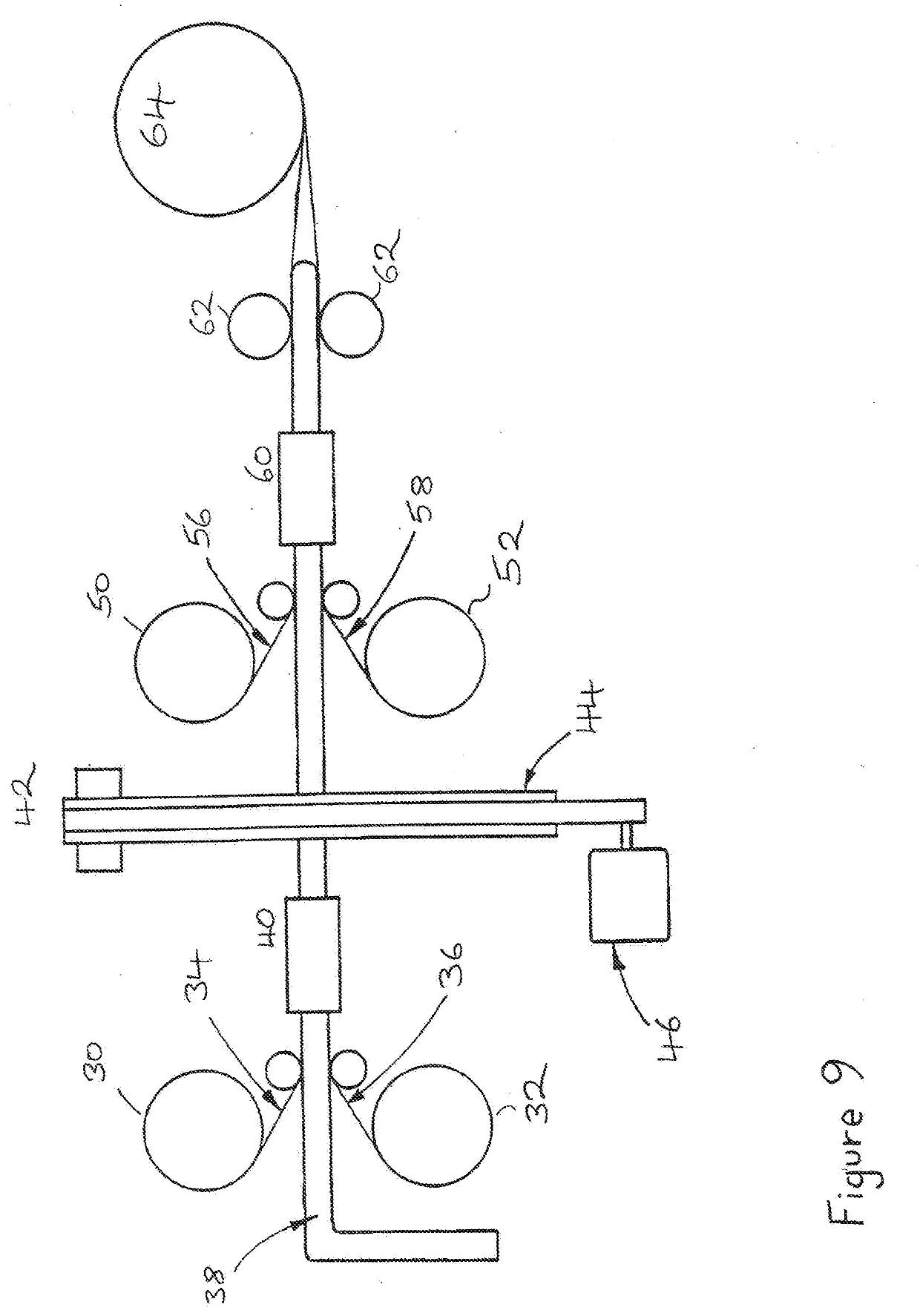

Image

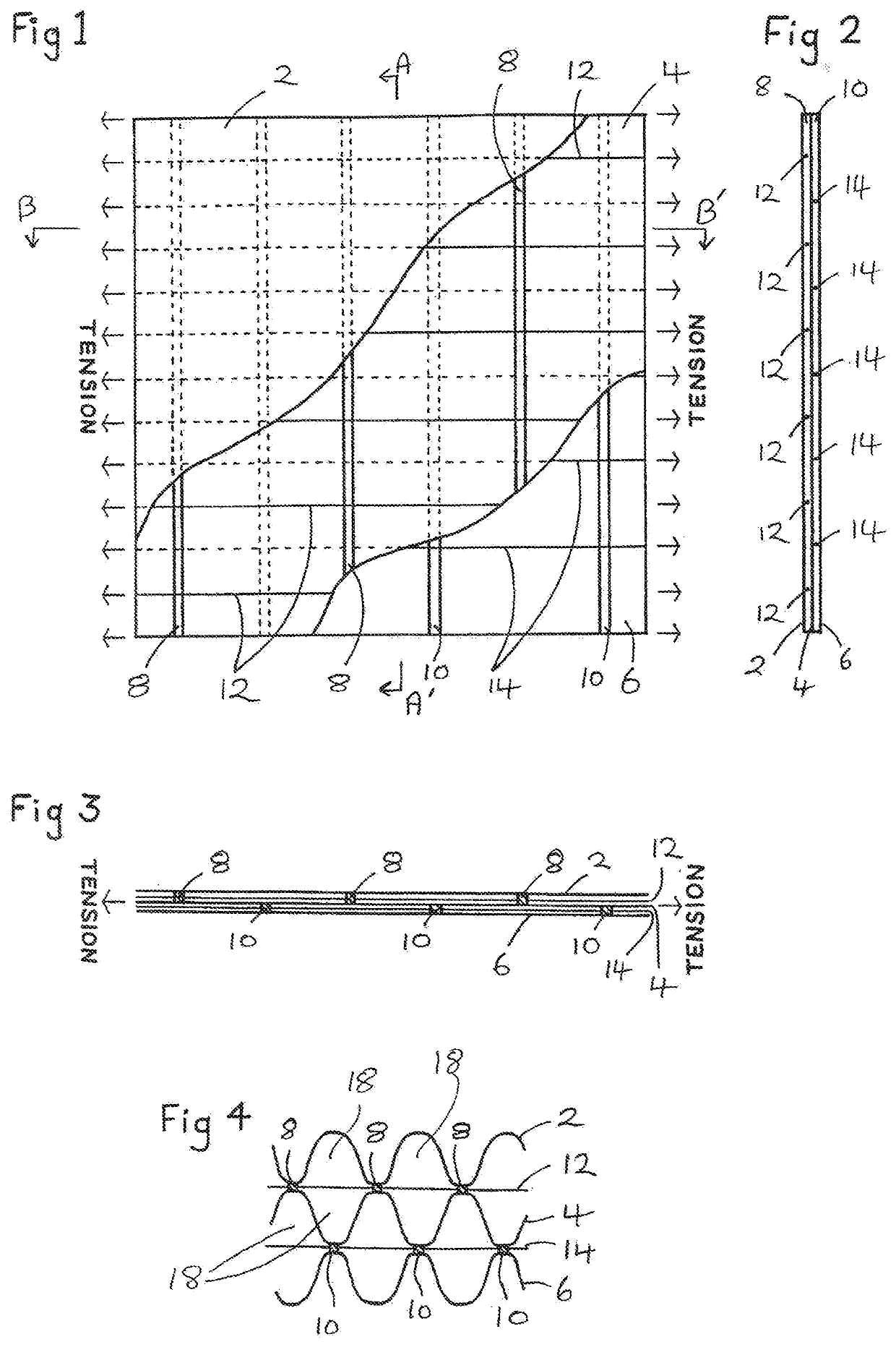
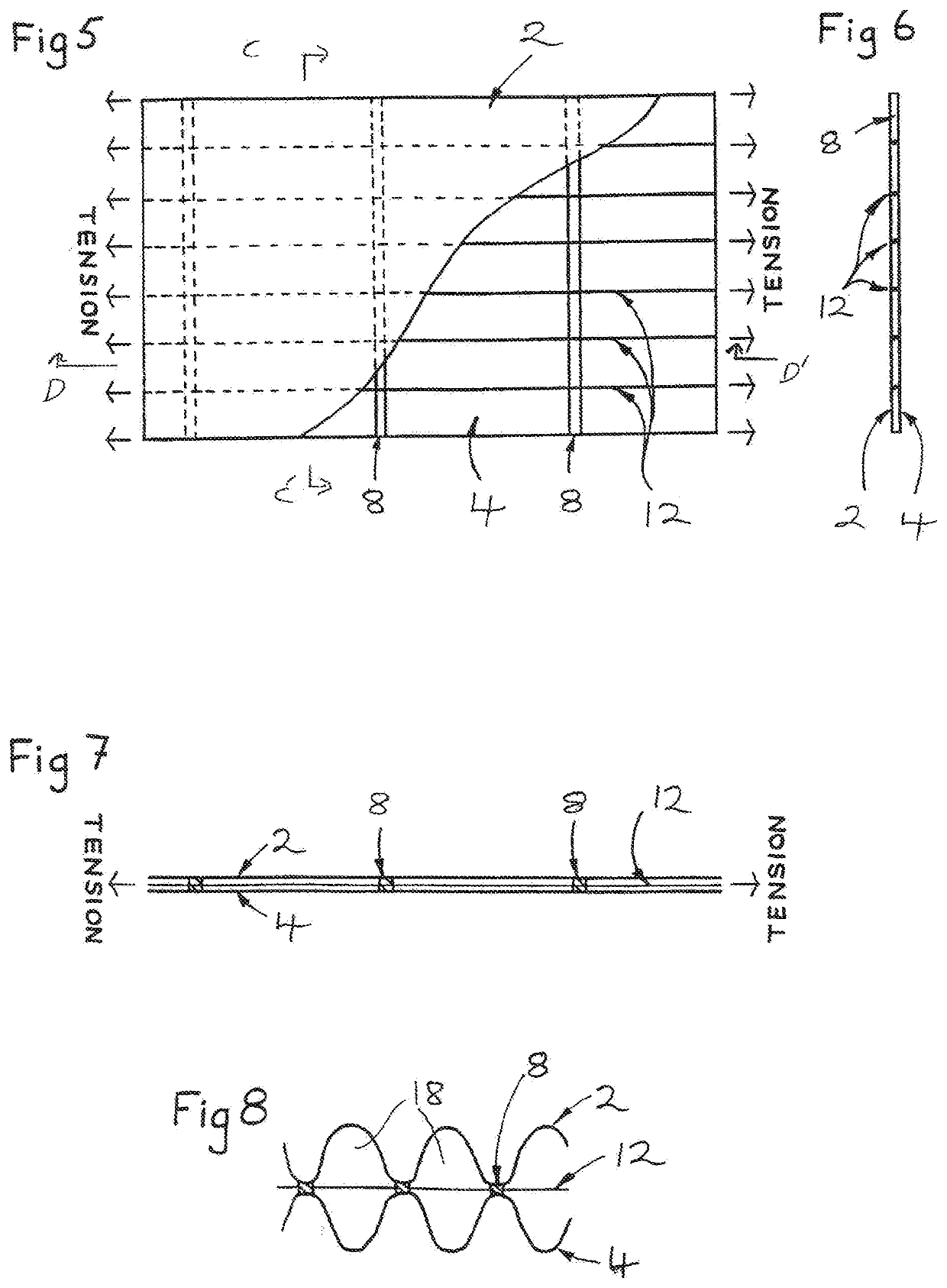
  • Thermal Insulating Material And Method
  • Thermal Insulating Material And Method
  • Thermal Insulating Material And Method

Examples


Embodiment Construction

[0021]The present invention provides unique ways of keeping patients in hospitals warm. The present invention particularly provides a method of preventing perioperative hypothermia before, during and after surgery. And the present invention provides a thermal insulating material that is used for making hospital blankets, hospital gowns, thermal wraps, and the like that can cover a patient to realize the advantages of the present invention.

[0022]According to a first aspect of the present invention, there is provided an insulating material, comprising first and second layers of primary material arranged to opposite sides of at least one elastic element, such that the insulating material can change between a first configuration wherein the at least one elastic element is stretched such that the at least one layer of primary material lies adjacent the at least one elastic element, and a second configuration wherein the at least one layer of primary material is bowed with respect to the ...


PUM

PropertyMeasurementUnit
Temperatureaaaaaaaaaa
Compositionaaaaaaaaaa
Densityaaaaaaaaaa

Abstract

An insulating material and a method using that material for preventing perioperative hypothermia in hospital patients. Hospital blankets, hospital gowns and thermal wraps are made with the insulating material, which comprises in one embodiment an inner layer and an outer layer of a nonwoven material and a middle layer of a polymer laminate material. The nonwoven material is a bicomponent coextruded spunbond nonwoven polypropylene and polyethylene textile and the polymer laminate material comprises polyethylene and metallised polyethylene terephthalate. The nonwoven material is arranged with an elastic such that the insulating material can change between a first configuration wherein the elastic is stretched such that the primary material lies adjacent to it, and a second configuration wherein the elastic is relaxed such that the primary material is bowed with respect to it, forming at least one cavity for entrapping air.

Description

CROSS REFERENCE TO RELATED APPLICATION[0001]NoneSTATEMENT REGARDING FEDERALLY SPONSORED RESEARCH OR DEVELOPMENT[0002]This invention is not the result of federally sponsored research.REFERENCE TO SEQUENCE LISTING, A TABLE, OR A COMPUTER PROGRAM LISTING, OR A COMPACT DISK APPENDIX[0003]NoneBACKGROUND1. Field of the Invention[0004]The present invention relates to a thermal insulating material particularly suitable for blankets and clothing to prevent heat-loss, and most particularly for use in hospital blankets and hospital gowns to prevent heat-loss by patients in a hospital setting.2. Description of Relevant Art[0005]Multi-layered materials and articles made from them that provide improved heat insulation without an increase in weight, as compared to conventional textile insulating materials, have been taught in International Patent Application No. PCT / GB99 / 01910 and its publication as WO 2000 / 00051, published Jan. 6, 2000, incorporated herein in its entirety by reference. A commerci...

Claims


Application Information

Patent Timeline
IPC IPC(8): A41D31/00A47G9/02A47G9/08A41D13/12D04H3/007D02G3/36D04H3/16D04H3/018D02G3/32B32B27/32B32B27/08B32B5/02B32B7/12B32B3/26B32B27/36
CPCA41D31/02Y10T428/24446A41D2400/10B32B5/028B32B2307/51D10B2501/04B32B7/12D02G3/328D04H3/16B32B27/08D10B2509/00B32B2250/24B32B5/022B32B27/32A47G9/08B32B27/36A41D2500/30A41D2500/52B32B2535/00A41D13/1245D02G3/36D10B2503/06D04H3/018B32B2437/00B32B3/266B32B2255/10A47G9/0223B32B2255/205B32B2262/0253A41D31/065D04H3/007B32B3/08B32B3/26B32B5/08B32B27/12B32B2255/02B32B2262/0207B32B2262/12B32B2307/304B32B2307/31B32B2307/416
Inventor RYDEN, DEREK
Owner BLIZZARD PROTECTION SYST
Learn More