Engine that includes blow-by-gas returning system

a technology of blow-by gas and engine, which is applied in the direction of machines/engines, functional valve types, combustion air/fuel air treatment, etc., can solve the problems of frozen moisture clogging the outlet of the pipe, the pipe is likely to be affected by coldness,

Active Publication Date: 2019-11-14
KUBOTA LTD
View PDF12 Cites 1 Cited by
  • Summary
  • Abstract
  • Description
  • Claims
  • Application Information

AI Technical Summary

Benefits of technology

[0010]The head cover receives heat from a cylinder head and thus becomes hot. According to an aspect of the present invention, blow-by gas returns to the cover intake-passage that forms part of the head cover that becomes hot. Therefore, even if sucked air is cold due to very low temperatures, for example, a temperature of the air rises while the air flows through the cover intake-passage. Therefore, moisture in blow-by gas that returns to the intake system, such as the compressor upstream suction passage, does not freeze or is less likely to freeze.
[0011]Consequently, an inventive structure allows moisture in blow-by gas to be less likely to freeze at a terminating end of the blow-by-gas passage where the blow-by-gas passage communicates with the intake system. Therefore, an improved engine that includes a blow-by-gas returning system that reduces the above inconvenience due to freezing at low temperatures as little as possible is provided.
[0012]The head cover receives heat from the cylinder head and thus becomes hot. According to a second aspect of the present invention, blow-by gas returns to the cover intake-passage that forms part of the head cover that becomes hot. Therefore, even if sucked air is cold due to very low temperatures, for example, a temperature of the air rises while the air flows through the cover intake-passage. Therefore, moisture in blow-by gas that returns to an intermediate passage does not freeze or is less likely to freeze.
[0013]Further, a bottom wall of the blow-by-gas passage includes a return hole, and a descending slope that becomes lower toward the return hole. Therefore, oil naturally flows by gravity even if the engine slightly tilts. Further, the descending slope improves an effect that attracts collected oil to the return hole.
[0014]Consequently, an inventive structure allows moisture in blow-by gas to be less likely to freeze at a terminating end of the blow-by-gas passage where the blow-by-gas passage communicates with the intake system. Therefore, an improved engine that includes a blow-by-gas returning system that reduces the above inconvenience due to freezing at low temperatures as little as possible is provided. Further, oil in blow-by gas returns well through the return hole into the improved engine that includes a blow-by-gas returning system, even if the improved engine slightly tilts.

Problems solved by technology

Since a pipe that returns blow-by gas to an intake system is generally disposed outside an engine, the pipe is likely to be affected by coldness.
The frozen moisture may clog the outlet of the pipe.

Method used


Image

  • Engine that includes blow-by-gas returning system
  • Engine that includes blow-by-gas returning system
  • Engine that includes blow-by-gas returning system

Examples


Embodiment Construction

[0030]Hereinafter, an engine that includes a blow-by-gas returning system according to a preferred embodiment of the present invention will be described with reference to the drawings. In the preferred embodiment, the engine is applied to an industrial diesel engine.

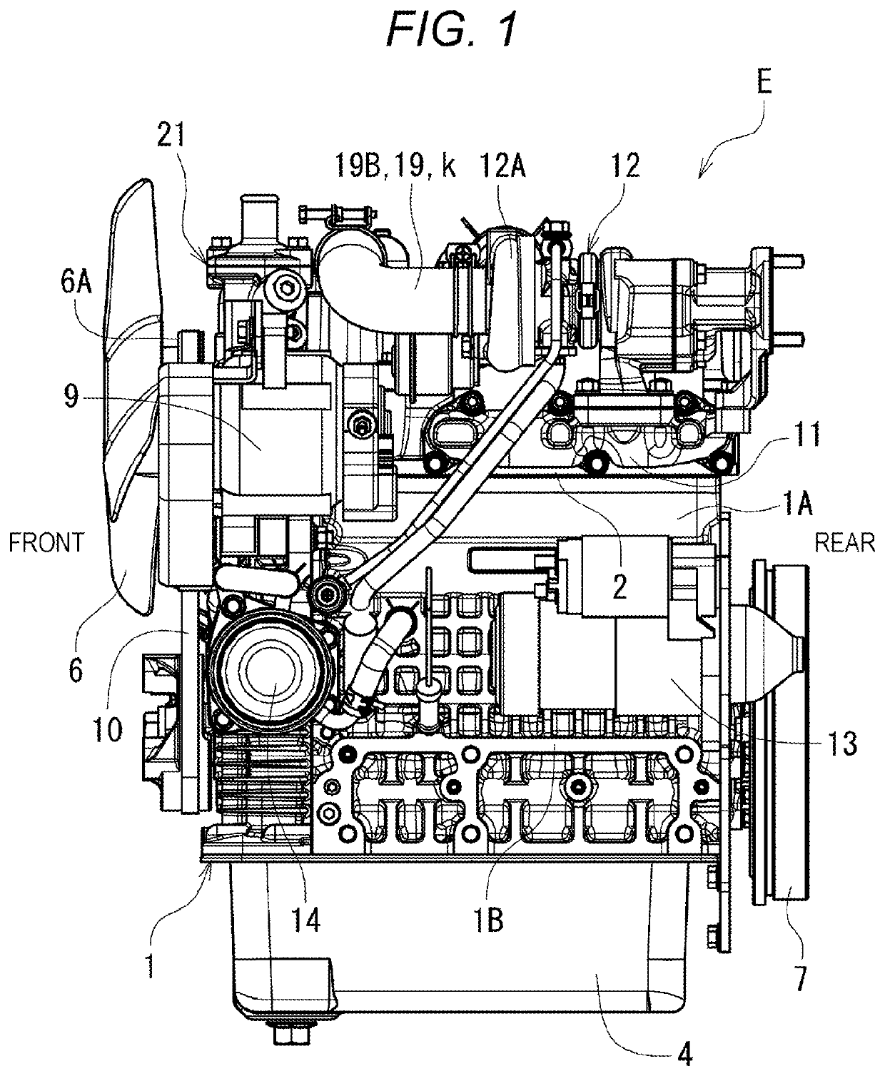
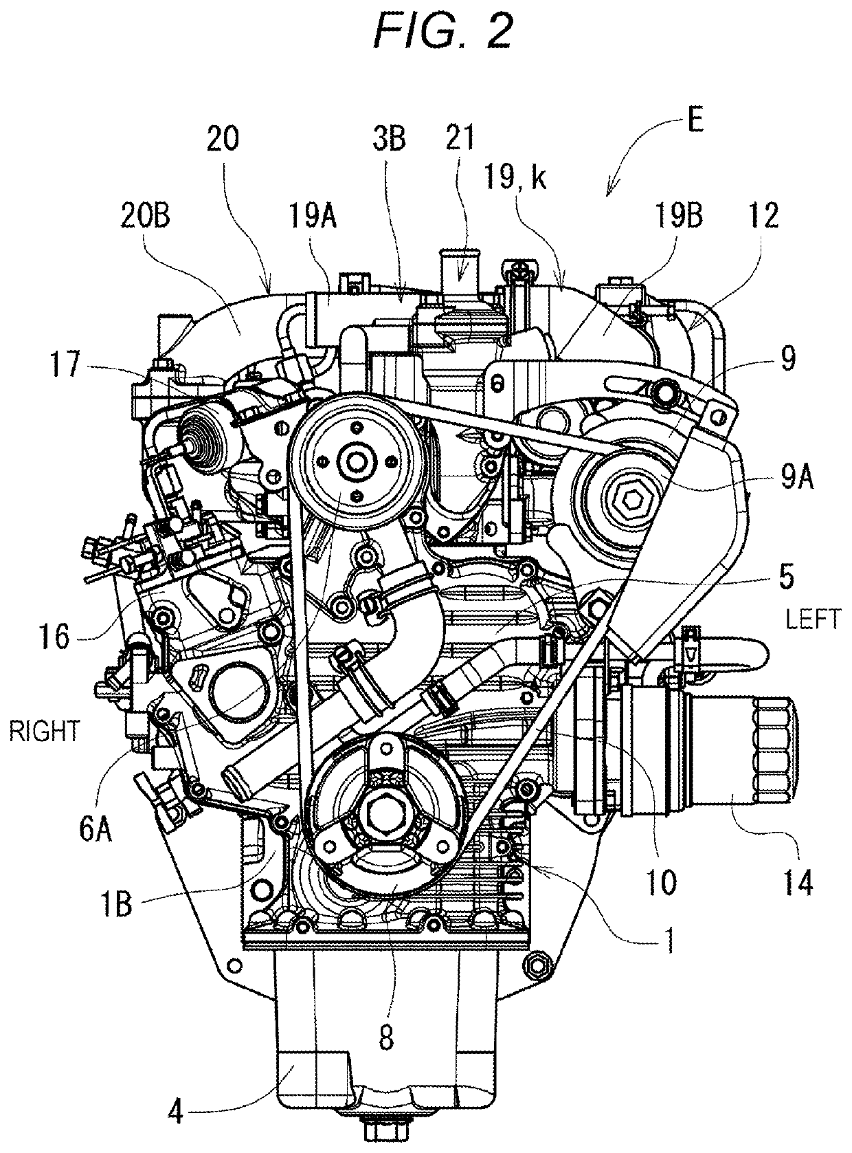
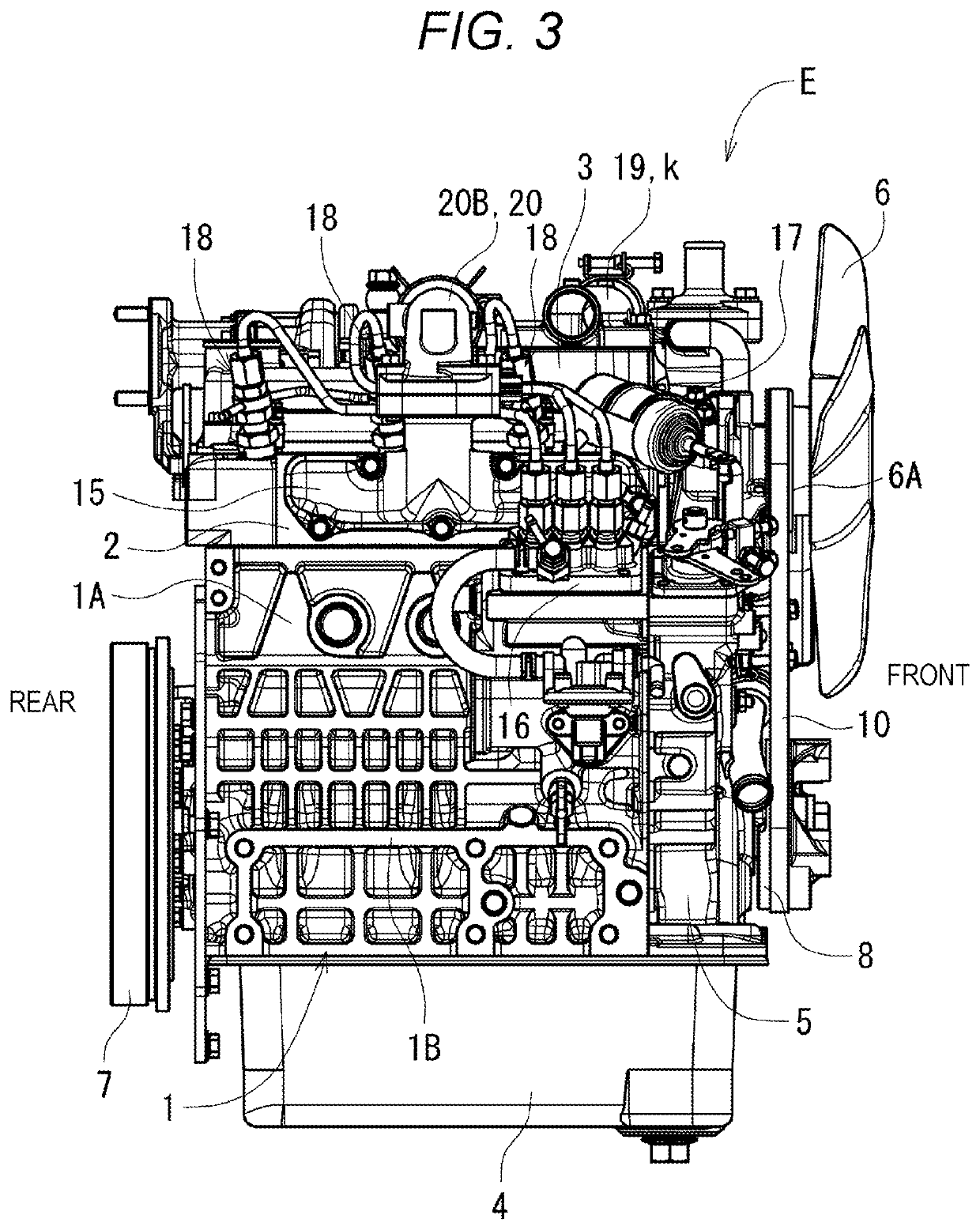
[0031]As illustrated in FIGS. 1 to 5, an industrial diesel engine (hereinafter simply referred to as the engine) E includes a cylinder block 1, a cylinder head 2 attached to a top of the cylinder block 1, a head cover 3 attached to a top of the cylinder head 2, and an oil pan 4 attached to a bottom of the cylinder block 1. A power transmitting case 5 is attached to a front end of the cylinder block 1. An engine cooling fan 6 is disposed in front of the power transmitting case 5. A flywheel 7 is disposed behind the cylinder block 1. An upper half of the cylinder block 1 forms cylinders 1A. A lower half of the cylinder block 1 forms a crankcase 1B.

[0032]For example, a power transmitting belt 10 and a water flange 21 are di...


PUM


Abstract

In an engine that includes a blow-by-gas returning system configured to direct blow-by gas within a crankcase to an intake system through an inside of a head cover, the intake system includes a cover intake-passage disposed at a blow-by-gas outlet of the head cover, and the cover intake-passage communicates with a blow-by-gas passage of the blow-by-gas outlet.

Description

BACKGROUND OF THE INVENTION(1) Field of the Invention[0001]The present invention relates to an engine that includes a blow-by-gas returning system.(2) Description of Related Art[0002]An engine includes a blow-by-gas returning system not to directly release blow-by gas that stays within a crankcase to the air. The blow-by-gas returning system returns blow-by gas that stays within a crankcase to an intake system, such as an intake passage. The blow-by gas that has returned to the intake system is mixed with new fuel-air mixture and burned. It is desirable to remove as much liquid components, such as oil (oil mist) and water, contained in blow-by gas, as possible before the blow-by gas is returned to an intake passage of an engine that includes a blow-by-gas returning system.[0003]Therefore, in many conventional engines, blow-by gas is returned to an intake system through a cylinder head and a head cover from a crankcase to allow liquid components to be easily collected within the engi...

Claims


Application Information

Patent Timeline
Patent Type & Authority Applications(United States)
IPC IPC(8): F01M13/04F02M35/10F02M35/04
CPCF02M35/10222F02M35/044F01M13/04F02M35/10157F01M13/00F02M25/06F01M2013/0455F02M35/10091F02M35/10288F01M13/0416F01M13/0011F01M2013/0494Y02T10/12F16K15/14
Inventor OSO, HIROKITANAKA, AKIRAKOYAMA, HIDEYUKIKANEKO, RINAOKADA, NOBUYOSHI
Owner KUBOTA LTD
Why Eureka
Try Eureka