
Retractable aircraft control surface

Inactive Publication Date: 2019-11-21
TRUHILL RICHARD MICHAEL
View PDF22 Cites 1 Cited by
  • Summary
  • Abstract
  • Description
  • Claims
  • Application Information

AI Technical Summary

Benefits of technology

The patent describes a vertical stabilizer / rudder assembly for aircraft that can be extended, retracted, or locked in different positions to provide stability and control, or high speed and stealth performance. The assembly reduces aerodynamic drag and radar cross-section, and can be adjusted at various angles to improve handling and efficiency. It allows for quick and easy changes to the aircraft configuration, and can be interchanged with other components without interfering with them.

Problems solved by technology

However, it also creates drag during straight and level flight.
For stealth aircraft, the presence of a vertical stabilizer / rudder is a great disadvantage.

Method used


Image

  • Retractable aircraft control surface
  • Retractable aircraft control surface
  • Retractable aircraft control surface

Examples


Embodiment Construction

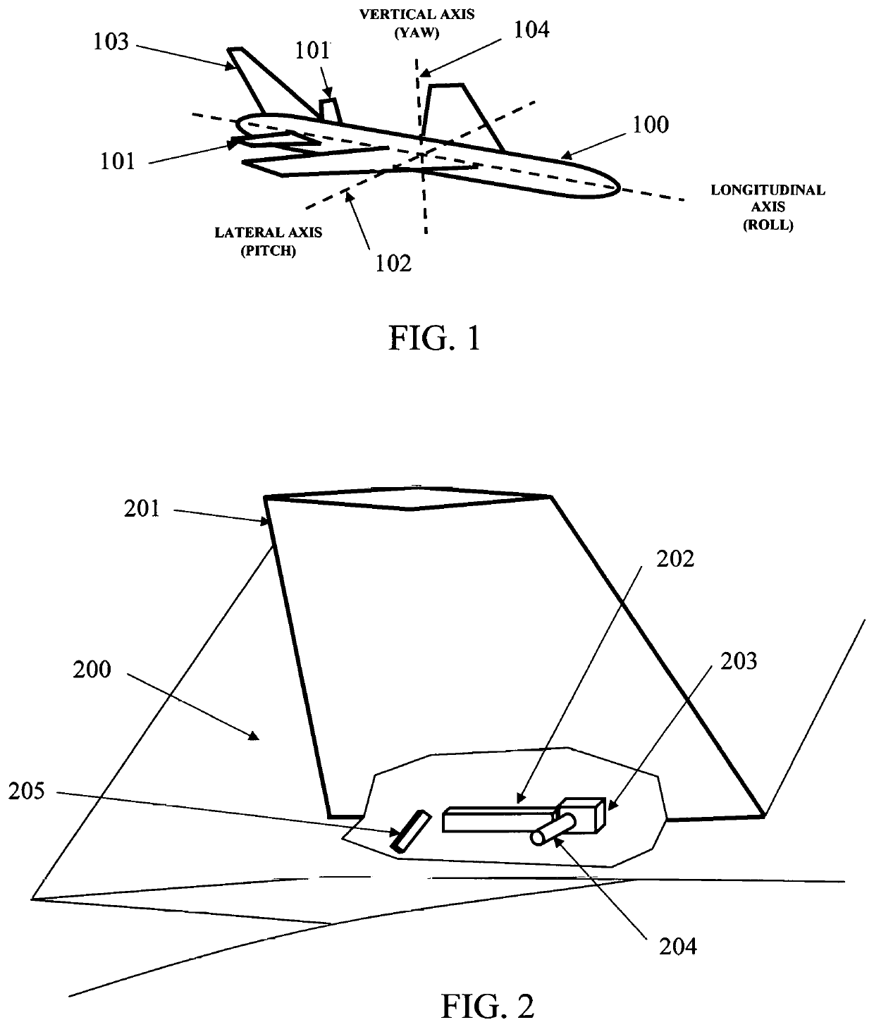
[0025]Referring to FIG. 1 the horizontal stabilizers / elevators 101 are used to control the aircraft 100 about the lateral or pitch axis 102, while the vertical stabilizer / rudder 103 is used to control the aircraft about the vertical or yaw axis 104.

[0026]FIG. 2 shows the components of a typical stabilizer / rudder assembly 201 installed on a typical aircraft 200. The components include: a pivotal connecting means 202, such as a hinge mechanism; a latching means 203, such as a locking mechanism; and a drive means 204, such as an actuator mechanism. All of said mechanisms are readily available “off the shelf” or easily constructed from available technology. For example, said actuator mechanism 204 could be mechanical, electrical as a conventional electric jackscrew, or hydraulic as a standard hydraulic cylinder. There would also be a rudder control mechanism 205, which is already part of any aircraft rudder assembly, and which allows the pilot to control the rudder by activating the rud...


PUM


Abstract

A modification to conventional aircraft empennage design, which is also adaptable to all-wing aircraft. Vertical stabilizer / rudder assemblies are hinged such that actuator and lock mechanisms are able to vary the aircraft empennage configuration from one with fully functional conventional vertical stabilizer(s) / rudder(s) to one with no vertical stabilizer / rudder.

Description

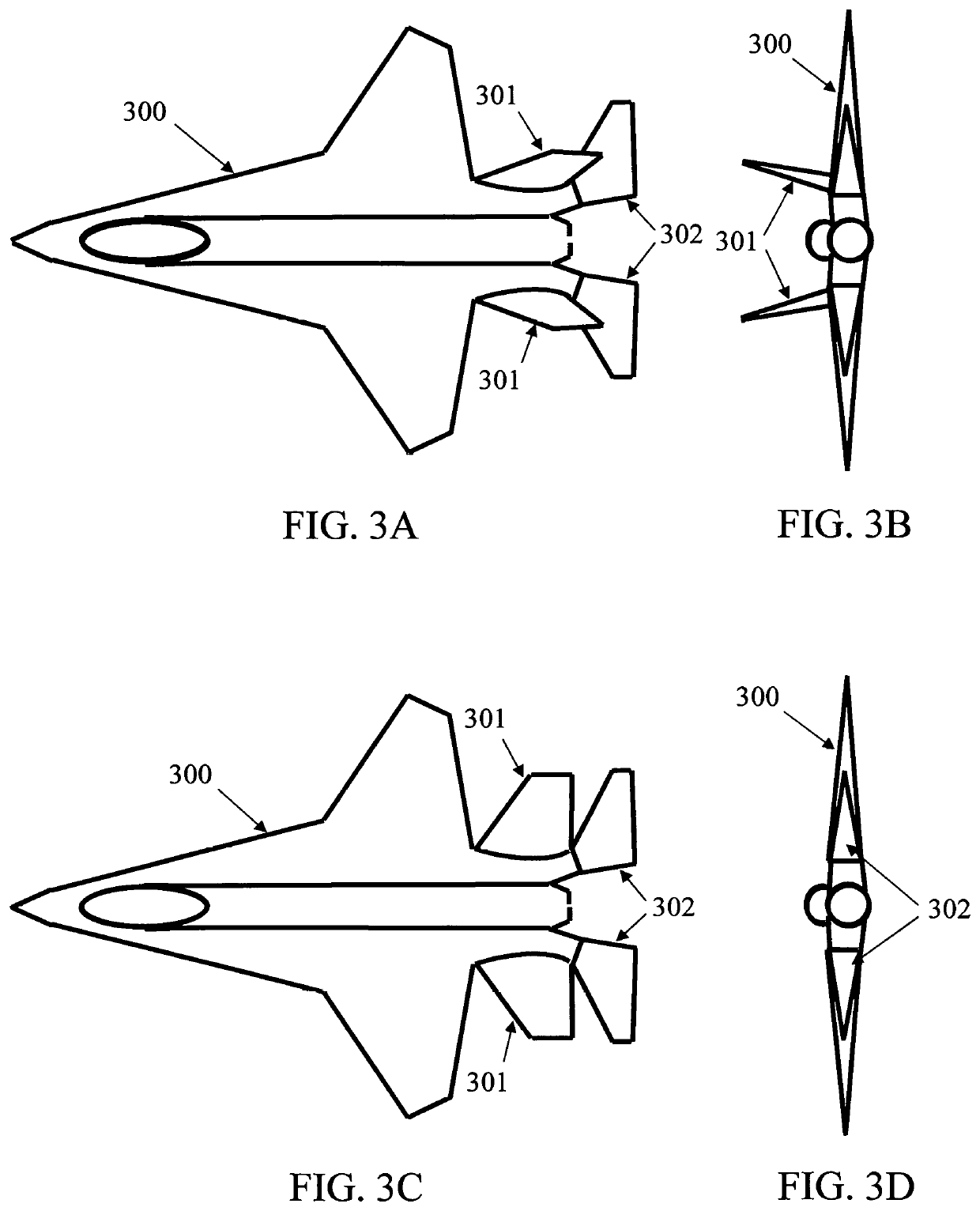
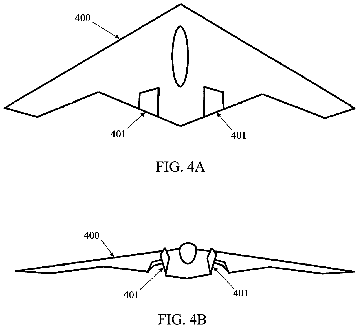
BACKGROUND OF THE INVENTION1. Field of the Invention[0001]The invention relates to aircraft empennage design, applicable to conventional aircraft design with a horizontal stabilizer and one or more vertical stabilizer / rudder assemblies, as well as all-wing aircraft design. The invention would allow an aircraft with one or more conventional vertical stabilizer / rudder assemblies to retract the stabilizer / rudder assemblies in flight from vertical to horizontal, creating less drag, thereby increasing speed, while also improving stealth characteristics. Conversely, the invention would allow an aircraft to extend the stabilizer / rudder assemblies in flight from horizontal to vertical, providing increased control and maneuverability of the aircraft. For example, the invention would allow an all-wing aircraft, which dues not have a vertical stabilizer, to fold one or more sections of the aircraft into a position from horizontal to vertical, or to any desired angle, thereby improving its hand...

Claims


Application Information

Patent Timeline
IPC IPC(8): B64C5/12B64C5/02B64C9/36
CPCB64C5/02B64C9/36B64C5/12B64C5/06B64C9/02B64C39/10Y02T50/10
Inventor TRUHILL, RICHARD MICHAEL
Owner TRUHILL RICHARD MICHAEL
Learn More