Inertial pneumatic wave energy device

a technology of pneumatic wave and energy device, which is applied in the direction of mechanical energy handling, mechanical equipment, machines/engines, etc., can solve the problems of computer failure, computer heat generation, and electrical power requirements of computers, and achieve the effect of reducing the cost and complexity of cooling the computing circuit of the computer

Active Publication Date: 2019-11-21
LONE GULL HLDG LTD
View PDF0 Cites 37 Cited by
  • Summary
  • Abstract
  • Description
  • Claims
  • Application Information

AI Technical Summary

Benefits of technology

[0017]Another aspect of the present invention is a novel type of computing apparatus which is integrated within a buoy that obtains the energy required to power its computing operations from waves that travel across the surface of the body of water on which the buoy floats. Additionally, these self-powered computing buoys employ novel designs to utilize their close proximity to a body of water and / or to strong ocean winds to significantly lower the cost and complexity of cooling their computing circuits. \

Problems solved by technology

First, computers require electrical power in order to operate and perform their calculations.
Secondly, computers generate heat.
The heat generated by computers can raise the temperatures of computers to levels that can cause those computers to fail, especially when the computers are located in close proximity to one another.
And, cooling, e.g. through air conditioners and / or air conditioning, requires and / or consumes significant amounts of electrical energy.

Method used


Image

  • Inertial pneumatic wave energy device
  • Inertial pneumatic wave energy device
  • Inertial pneumatic wave energy device

Examples


embodiment 100

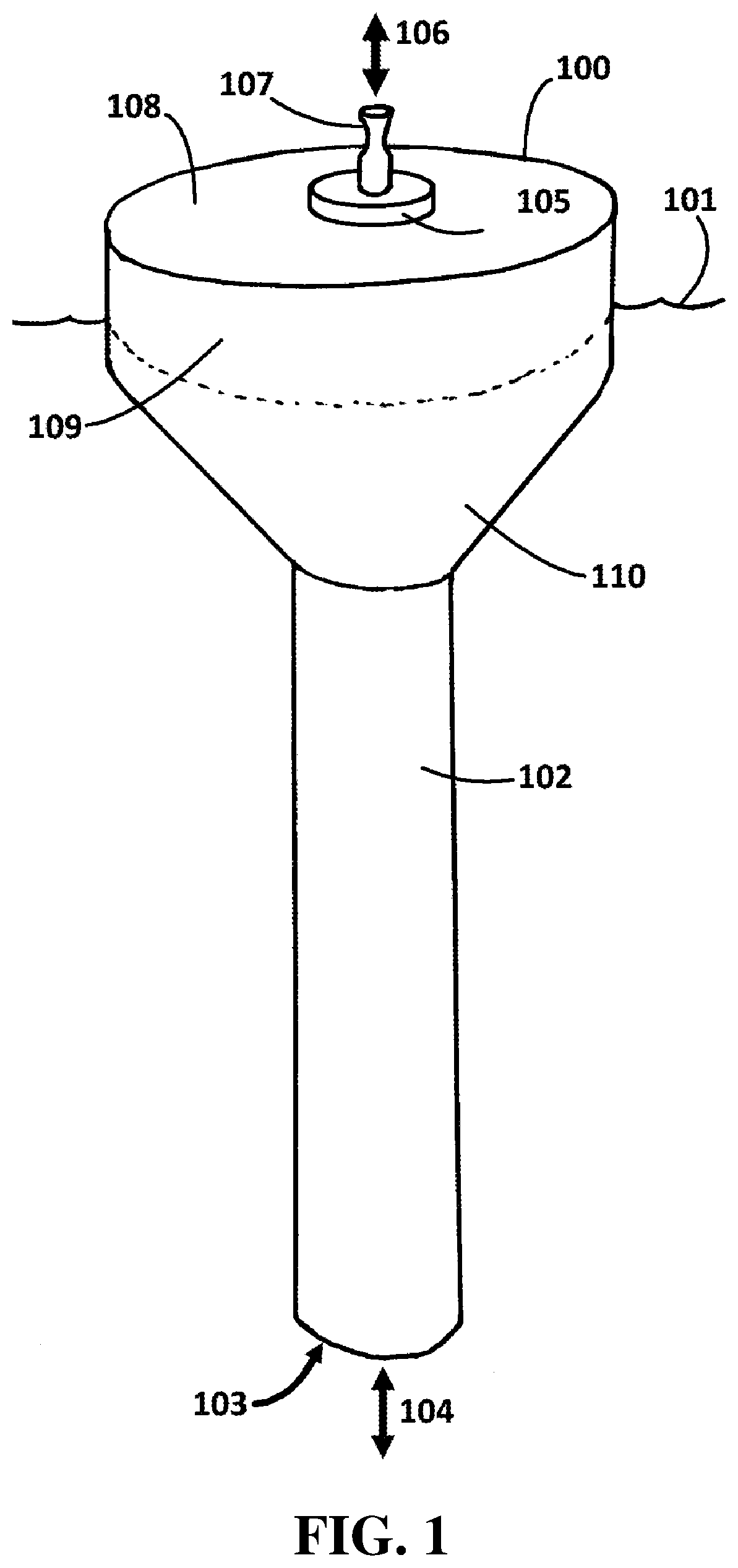
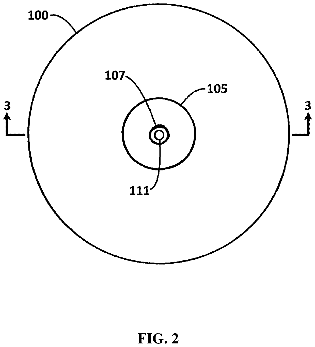
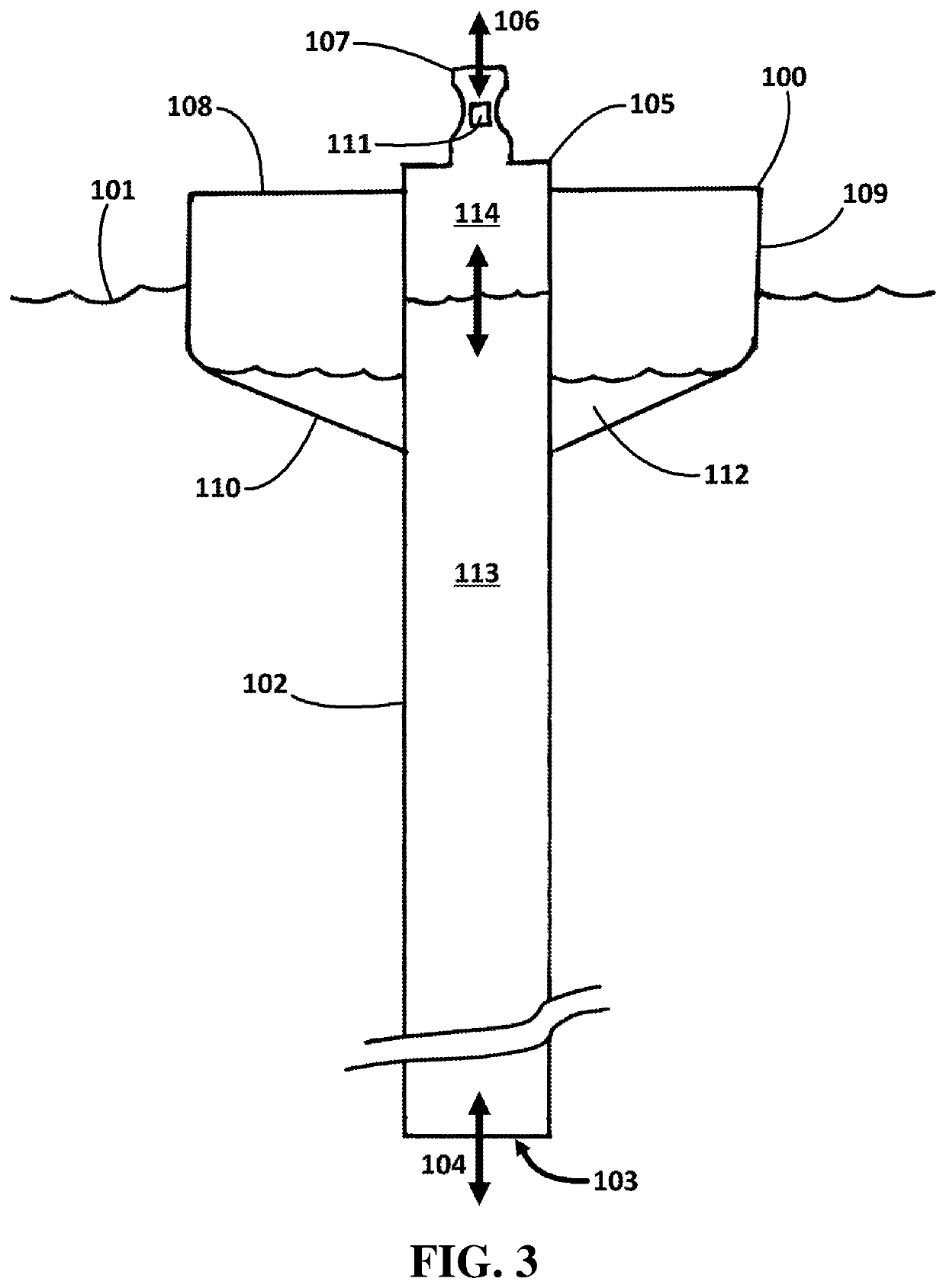
[0595]FIG. 1 shows a side perspective view of an embodiment of the present invention. The embodiment 100 floats adjacent to an upper surface 101 of a body of water. The embodiment incorporates a tubular water column 102, a lower end 103 of which is open to the water 101. As the embodiment moves up and down in response to passing waves, water moves 104 in and out of the open bottom 103 of the water column 102. Water moves 104 in and out of the open bottom 103 of the water column at least in part due to wave-induced changes in the draft of that portion of the water column and at least in part due to vertical movements of the embodiment in response to wave heave.

[0596]As the level of the water within the water column 102 oscillates, a pocket of air trapped in an upper portion 105 of the water column is alternately compressed and expanded. As the pocket of air expands and contracts in response to variations in the level of the water enclosed within the water column 102, air is alternate...

embodiment 120

[0603]FIG. 4 shows a side perspective view of an embodiment of the present invention. The embodiment 120 floats adjacent to an upper surface 121 of a body of water. The embodiment incorporates a tubular water column 122 a lower end 123 of which is open to the water. As the embodiment moves up and down in response to passing waves, water moves 124 in and out of the open bottom 123 of the water column 122. Water moves 124 in and out of the open bottom 123 of the water column 122 at least in part due to wave-induced changes in the draft of that portion of the water column and at least in part due to vertical movements of the embodiment in response to wave heave.

[0604]As the level of the water within the water column 122 oscillates, a pocket of air trapped in an upper portion of the water column 122 (within a portion of the water column positioned inside the buoy 130) is alternately compressed and expanded. As the pocket of air expands in response to downward movements of the upper surf...

embodiment 170

[0633]As the buoy 170 rises and falls in response to waves traveling across the surface 177 of the body of water on which the buoy floats, the water partially enclosed within the water column 171 / 176 rises and falls, as water flows 178 into, and out of, the water column's mouth 179. The water 180 within the water column 171 / 176 rises and falls 181, at least in part, due to the changes in the pressure of the water adjacent to the bottom mouth 179 of the water column that result from changes in the depth of the bottom mouth of the water column. The depth of, and water pressure around, the bottom mouth of the water column change, at least in part, because as waves lift and let fall the buoy, the buoy's vertical movements are imperfectly synchronized with the surfaces of those waves and with the movements of the embodiment, thereby effectively changing the depth of the water column's mouth 179. The water 180 within the water column 171 / 176 also rises and falls 181, at least in part, due...


PUM


Abstract

A buoyant wave energy device is disclosed that incorporates an open-bottomed tube of substantial length in which is partially enclosed a first body of water that oscillates in response to wave action. The device incorporates a buoy to which an upper end of the tube is connected and inside of which is trapped a second body of water of substantial mass. A differential phase in the oscillations of the water trapped in the tube, and the oscillations of the buoy of augmented mass, result in the periodic compression of a pocket of air trapped at the top of the tube, and in the subsequent expulsion of pressurized air through a turbine, thereby generating electrical power.

Description

CROSS-REFERENCES TO RELATED APPLICATIONS[0001]This application claims priority from U.S. Ser. No. 62 / 693,373, filed Jul. 2, 2018. and U.S. Ser. No. 62 / 672,579, filed May 17, 2018, the contents of which are incorporated herein by reference in their entirety.BACKGROUND[0002]Large-scale computing currently has at least two significant limitations and / or drawbacks, each of which is solved by the present invention. First, computers require electrical power in order to operate and perform their calculations. Electrical power is required to energize CPUs. Electrical power is required to energize random-access memory. Electrical power is required to energize shared and / or more persistent memory (e.g. hard disks). Electrical power is required to energize switches, routers, and other equipment supporting network connections between computers.[0003]As society's reliance on computers and computing increases, the portion of the world's energy budget that is consumed by computers and computing al...

Claims


Application Information

Patent Timeline
Patent Type & Authority Applications(United States)
IPC IPC(8): F03B13/24H02K7/18
CPCF03B13/24H02K7/1823F05B2220/706F03B13/142F05B2240/93F05B2240/95F05B2240/133Y02E10/30
Inventor SHELDON-COULSON, GARTH ALEXANDERMOFFAT, BRIAN LEEPLACE, DANIEL WILLIAM
Owner LONE GULL HLDG LTD
Why Eureka
Try Eureka