Bistable switchable liquid crystal private device

a liquid crystal display and switchable technology, applied in non-linear optics, instruments, optics, etc., can solve the problem of unsuitability within the size constraints of portable computing devices, and achieve the effect of widening the distribution of light and enhancing the screening of off-axis ligh

Active Publication Date: 2019-11-21
SHARP KK
View PDF3 Cites 50 Cited by
  • Summary
  • Abstract
  • Description
  • Claims
  • Application Information

AI Technical Summary

Benefits of technology

[0007]The present disclosure describes a display system that is electrically switchable between a narrow angle view mode (also referred to as a private mode) and a wide angle view mode (also referred to as a public mode). With the described configurations, a display device operates in different states that enable both enhanced screening of off-axis light of the private mode, and wider distribution of light for the public mode.

Problems solved by technology

Electronic switching methods have been developed to avoid the need for moving parts such as described above, which may be unsuitable within the size constraints of portable computing devices.

Method used


Image

  • Bistable switchable liquid crystal private device
  • Bistable switchable liquid crystal private device
  • Bistable switchable liquid crystal private device

Examples


Embodiment Construction

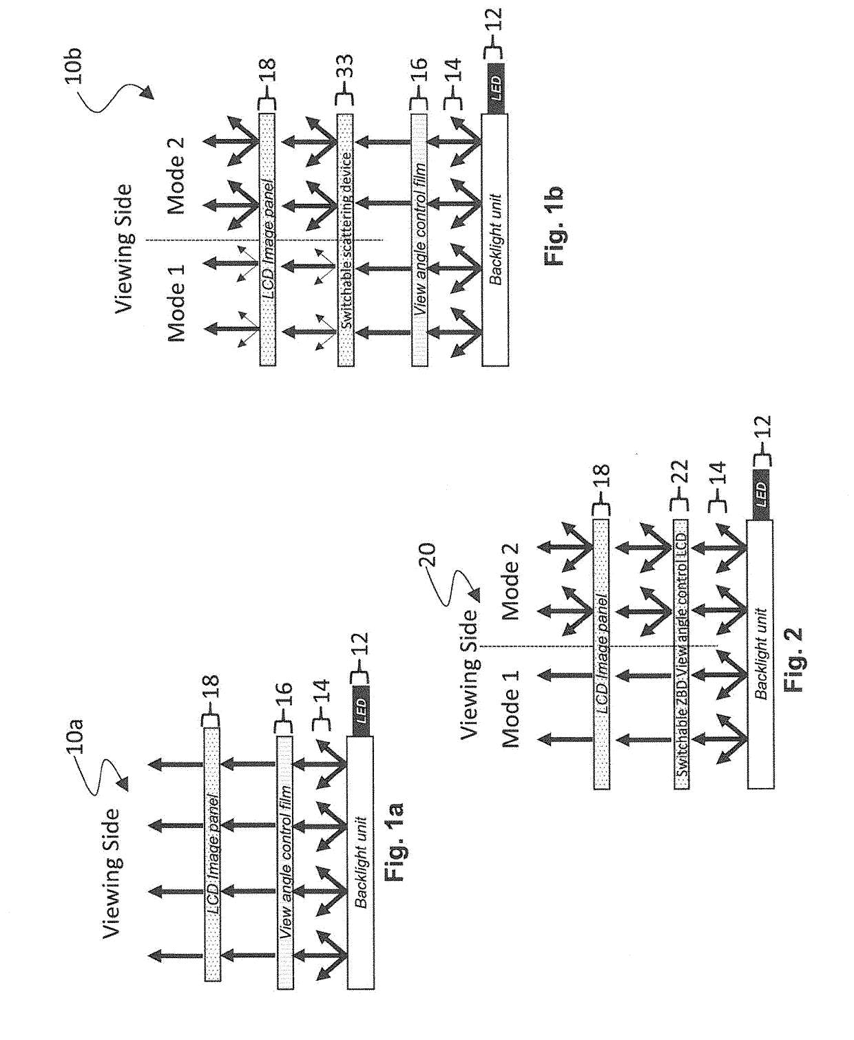
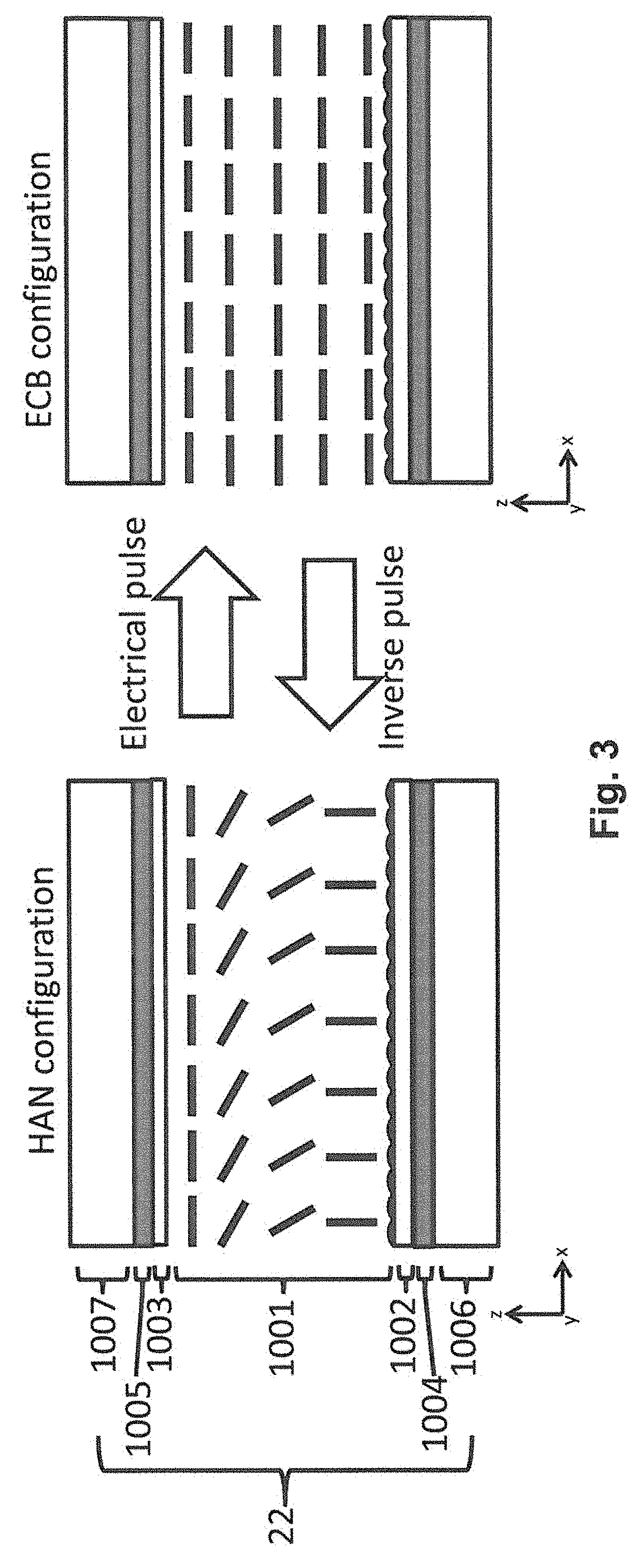
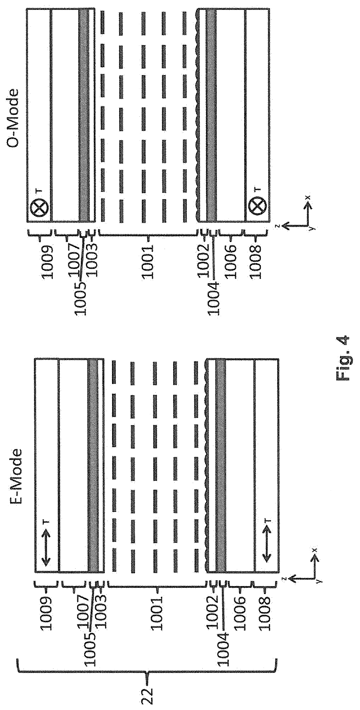
[0037]Embodiments of the present invention will now be described with reference to the drawings, wherein like reference numerals are used to refer to like elements throughout. It will be understood that the figures are not necessarily to scale.

[0038]In the context of the layering of the components of device configurations described herein, the viewing side, sometimes also referred to as the outer side of the LCD or associated display system, is the side at which a person typically would look at or view images on the LCD, from which images may be provided for projection, and the like. Relative to the illustrations in the drawings, the top or upper side of the device configuration, or of a component or layer of the device configuration, is at the top of the respective drawings, i.e., is closer to the viewing side. The side opposite to the viewing side is referred to as the non-viewing side, bottom, lower, or back side, or in some cases the backlight-side of the LCD or display system.

[...


PUM

PropertyMeasurementUnit
bias voltage Vbiasaaaaaaaaaa
bias voltageaaaaaaaaaa

Abstract

A switchable view angle control device includes an electrically switchable zenithal bistable liquid crystal display view angle control liquid crystal device (ZBD view angle control LCD) that is operable in a first state and a second state; a front polarizer located on a viewing side of the switchable ZBD view angle control LCD; and a polarized light source located on a non-viewing side of the switchable ZBD view angle control LCD that emits light that is polarized in a first direction. When the switchable ZBD view angle control LCD in the first state, the view angle control device operates in a narrow angle view mode in which the polarization of the light from the polarized light source is changed by the switchable ZBD view angle control LCD to be polarized in a second direction that is at least partially absorbed by the front polarizer, and on-axis light passes through the switchable ZBD view angle control LCD and the front polarizer. When the switchable ZBD view angle control LCD is in the second state, the view angle control device operates in a wide angle view mode in which the polarization state of the light from the polarized light source is not changed by the switchable ZBD view angle control LCD and passes through the front polarizer.

Description

TECHNICAL FIELD[0001]The present invention relates to liquid crystal display devices, and more specifically to liquid crystal display devices that are switchable between a narrow angle view mode (also referred to as a private mode) and a wide angle view mode (also referred to as a public mode).BACKGROUND ART[0002]With the increased use of portable computing devices having liquid crystal displays (LCDs), such as smartphones, laptop computers, tablet computers and the like, users have become concerned with other individuals being able to read sensitive or private information. Accordingly, many portable computing devices are operable in a narrow angle view mode (also referred to as a private mode) in which information is largely viewable only by an on-axis viewer, and a separate wide angle view mode (also referred to as a public mode) in which information is generally viewable at wider viewing angles by off-axis viewers within the capabilities of the device. Such devices typically are ...

Claims


Application Information

Patent Timeline
Patent Type & Authority Applications(United States)
IPC IPC(8): G02F1/13G02F1/1335G02F1/1337G02F1/137G02F1/1343
CPCG02F1/1323G02F1/13362G02F1/137G02F1/1337G02F1/133528G02F2001/133742G02F2001/133738G02F2201/122G02F1/134309G02F1/13471G02F1/133738G02F1/133742
Inventor ACREMAN, ANDREWSMITH, NATHAN JAMES
Owner SHARP KK
Why Eureka
Try Eureka