Report nsa/sa nr indicator

a technology of nsa/sa and indicator, applied in the direction of electrical equipment, wireless communication, etc., can solve the problems of frequent error cases, 5g network deployment, and 5g network deployment methods

Active Publication Date: 2019-11-21
TELEFON AB LM ERICSSON (PUBL)
View PDF0 Cites 26 Cited by
  • Summary
  • Abstract
  • Description
  • Claims
  • Application Information

AI Technical Summary

Benefits of technology

[0025]The present disclosure introduces new information in existing UE measurements on NR. In some embodiments, the new information comprises the inclusion of information relating to the ability of the UE to camp on the neighbor NR cell or not. This new information is essential for the mobility / ANR functionality in the network to assist RAN (eNB / gNB) with optimal decision making in various scenarios.
[0026]Certain embodiments disclosed herein may provide one or more technical advantages including: (i) improved ANR functionality; (ii) improved mobility handling and reduced handover failure; (iii) end user performance; and (iv) simplified network management.
[0028]Regarding the improved mobility handling and reduced handover failure, the current disclosure allows the avoidance of handover initiation towards non-stand-alone NR neighbors which would result into failure.
[0029]Regarding the improved end user performance, the current disclosure allows the avoidance of probable UE performance degradation due to failed handover. Moreover, the knowledge about neighbor NR cell (NSA / SA indicator), helps an eNB / gNB make optimized RAN decisions and actions further based on the UE capabilities and network characteristics.
[0030]Regarding the simplified network management, manual planning of neighboring cell relations may be reduced.

Problems solved by technology

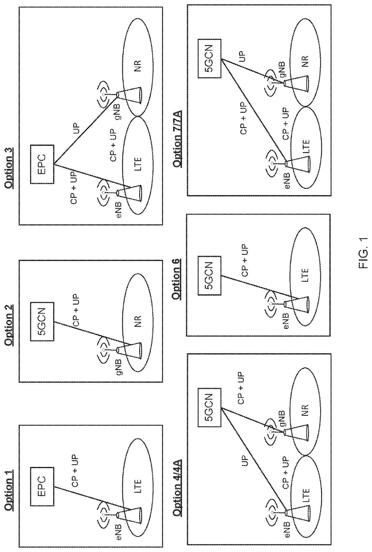
A mixture of different deployment options in the same network is inevitable and this mixture may cause problems.
Accordingly, due to the various functionalities of the different NR cells and various UE capabilities, conventional methods of 5G network deployment may lead to frequent error cases.
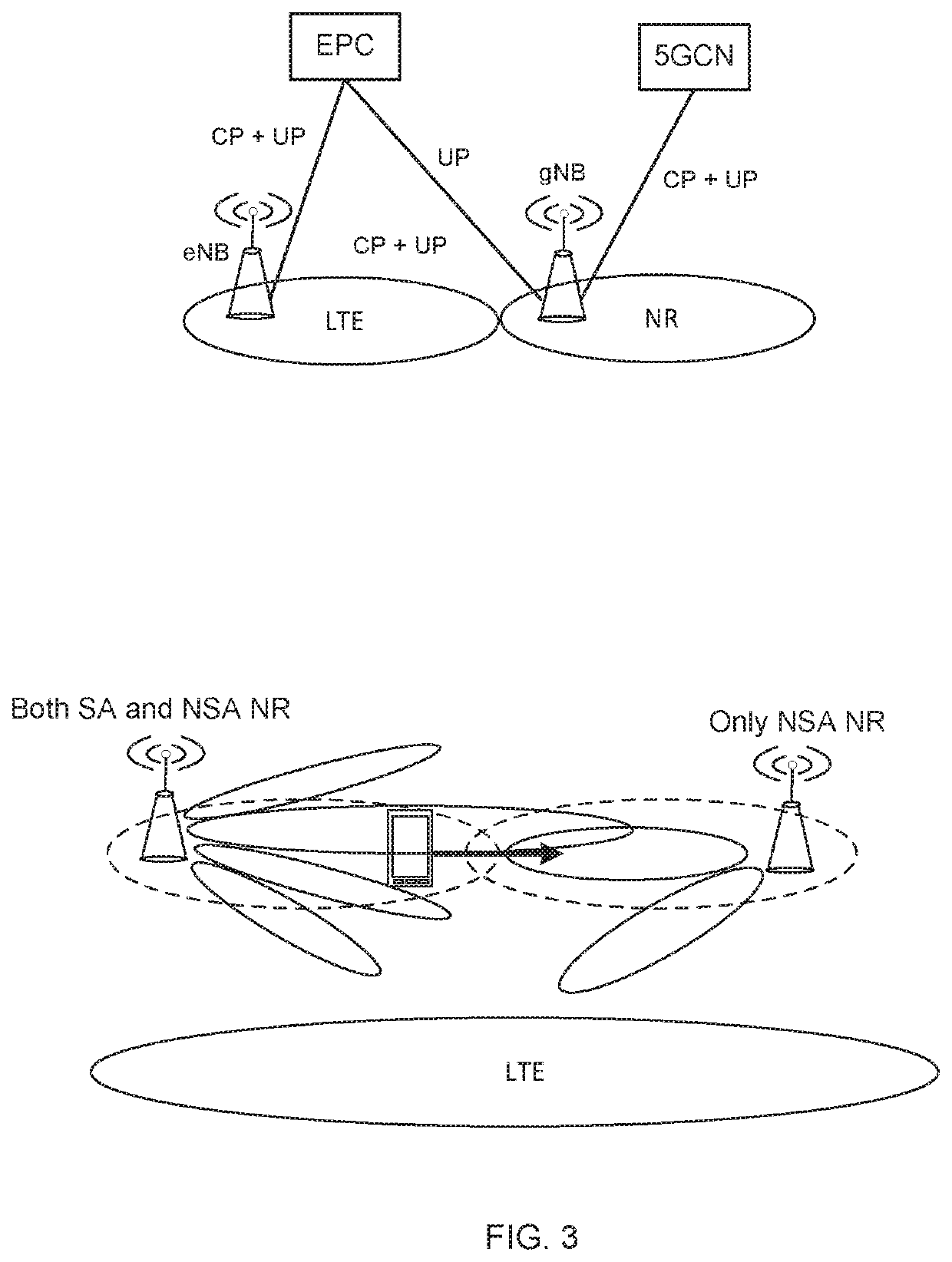
For example, a scenario in which a problem may arise in conventional methods of 5G network deployment is when a UE connected to an LTE-EPC eNodeB sends a measurement report with an NR cell-A and the serving eNodeB wants to perform an inter-RAT handover and / or release and redirect to that NR cell.
If the target NR cell is NSA, this will lead to errors.
Another scenario in which a problem may arise in conventional methods of 5G network deployment is when a UE connected to an LTE-EPC eNodeB sends a measurement report with an NR cell-A and the serving eNodeB wants to perform EN-DC.
If the NR cell is an SA cell that is not supported, this will also lead to errors.
Yet another scenario in which a problem may arise in conventional methods of 5G network deployment is when a UE connected to an NR gNodeB sends a measurement report with an NR cell-A and the serving gNodeB wants to perform a handover.
If that NR cell is a NSA cell that is not supported, this also could lead to errors.
However, it is not possible to execute a handover in this scenario because the target is a NSA only NR cell with no connection to 5GCN.
However, there may also be problems in terms of inter-node actions the serving node can take.
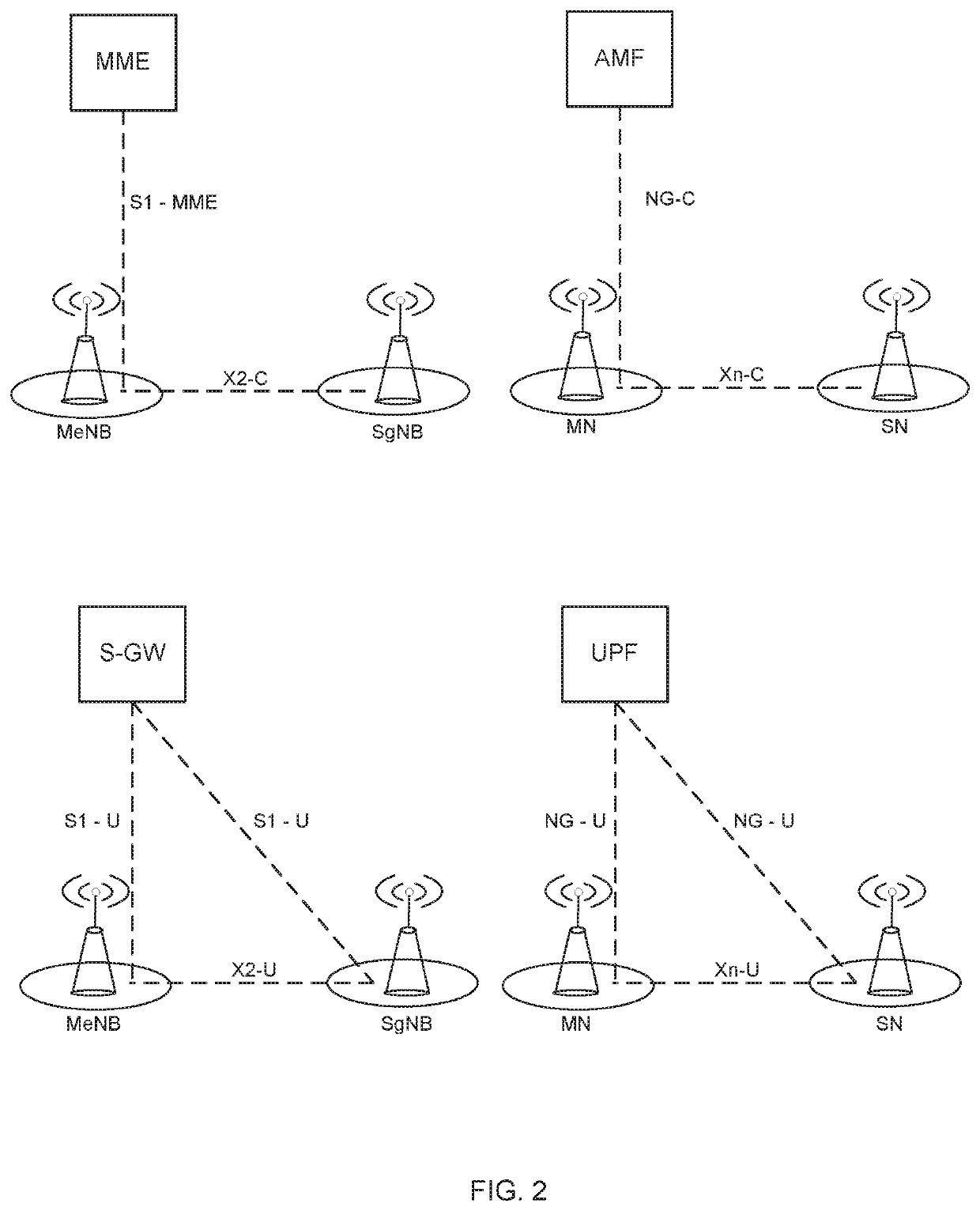
For example, it may not be possible for the serving node to setup X2 connectivity with an NR node handling an SA cell.
As another example, it may not be possible for the serving node to setup Xn connectivity with an NR node handling an NSA cell.
With existing solutions for NR measurement reporting based on Physical Cell Identity (PCI), there does not exist a proper way for the serving node (either an NR node or an LTE node or a node from any RAT capable of performing inter-RAT mobility and / or DC setup) to know whether the target NR cell supports NSA NR, SA NR or both.
This inability of the serving node to know whether the target NR cell supports NSA NR, SA NR or both may lead to problems.
For example, the network would not be able to determine whether to setup an X2 interface, to setup of an Xn interface, or determine whether there are not any possible inter-node setups available, etc.

Method used


Image

  • Report nsa/sa nr indicator
  • Report nsa/sa nr indicator
  • Report nsa/sa nr indicator

Examples


embodiments

Group C Embodiments

[0257]C1. A wireless device comprising:

[0258]processing circuitry configured to perform any of the steps of any of the Group A embodiments; and

[0259]power supply circuitry configured to supply power to the wireless device.

[0260]C2. A base station comprising:

[0261]processing circuitry configured to perform any of the steps of any of the Group B embodiments;

[0262]power supply circuitry configured to supply power to the wireless device.

[0263]C3. A user equipment (UE) comprising:

[0264]an antenna configured to send and receive wireless signals;

[0265]radio front-end circuitry connected to the antenna and to processing circuitry, and configured to condition signals communicated between the antenna and the processing circuitry;

[0266]the processing circuitry being configured to perform any of the steps of any of the Group A embodiments;

[0267]an input interface connected to the processing circuitry and configured to allow input of information into the UE to be processed by ...


PUM


Abstract

A wireless device configured to acquire network support information associated with a neighbor cell, wherein the network support information indicates that the neighbor cell supports a Stand-Alone (SA) mode of operation and / or a Non-Stand-Alone (NSA) mode of operation; and transmit to a serving network node a report comprising identification information associated with the neighbour cell and the network support information indicating that the neighbor cell supports a SA mode of operation and / or a NSA mode of operation. A serving network node configured to receive a report transmitted by a wireless device, wherein the report comprises identification information associated with the neighbor cell and network support information indicating that the neighbor cell supports a Stand-Alone (SA) mode of operation and / or a Non-Stand-Alone (NSA) mode of operation; and determine, based on the report, a type of interface to establish between the serving network node and the neighbor network node.

Description

INTRODUCTION[0001]Generally, all terms used herein are to be interpreted according to their ordinary meaning in the relevant technical field, unless a different meaning is clearly given and / or is implied from the context in which it is used. All references to a / an / the element, apparatus, component, means, step, etc. are to be interpreted openly as referring to at least one instance of the element, apparatus, component, means, step, etc., unless explicitly stated otherwise. The steps of any methods disclosed herein do not have to be performed in the exact order disclosed, unless a step is explicitly described as following or preceding another step and / or where it is implicit that a step must follow or precede another step. Any feature of any of the embodiments disclosed herein may be applied to any other embodiment, wherever appropriate. Likewise, any advantage of any of the embodiments may apply to any other embodiments, and vice versa. Other objectives, features and advantages of t...

Claims


Application Information

Patent Timeline
Patent Type & Authority Applications(United States)
IPC IPC(8): H04W36/00
CPCH04W36/0083H04W92/20H04W36/0061H04W36/0094H04W36/00
Inventor PAKNIAT, PARISADA SILVA, ICAROMILDH, GUNNAR
Owner TELEFON AB LM ERICSSON (PUBL)
Why Eureka
Try Eureka