Method for controlling an electronically slip-controllable power braking system

a technology of power braking and electronic control, which is applied in the direction of braking systems, braking components, transportation and packaging, etc., can solve the problem that the discharged pressure medium is no longer available for subsequent use, and achieve the effect of small overall volume and cost-effectiveness

Active Publication Date: 2019-11-28
ROBERT BOSCH GMBH
View PDF0 Cites 2 Cited by
  • Summary
  • Abstract
  • Description
  • Claims
  • Application Information

AI Technical Summary

Benefits of technology

[0019]An example control method in accordance with the present invention may offer the advantage that an existing vehicle braking system may be equipped with a plunger unit of more compact dimensions, and therefore requires a smaller overall volume, and may ultimately be provided more cost-effectively.

Problems solved by technology

Discharged pressure medium is therefore no longer available for subsequent brake pressure buildups by plunger unit 60, however.

Method used


Image

  • Method for controlling an electronically slip-controllable power braking system
  • Method for controlling an electronically slip-controllable power braking system

Examples


Embodiment Construction

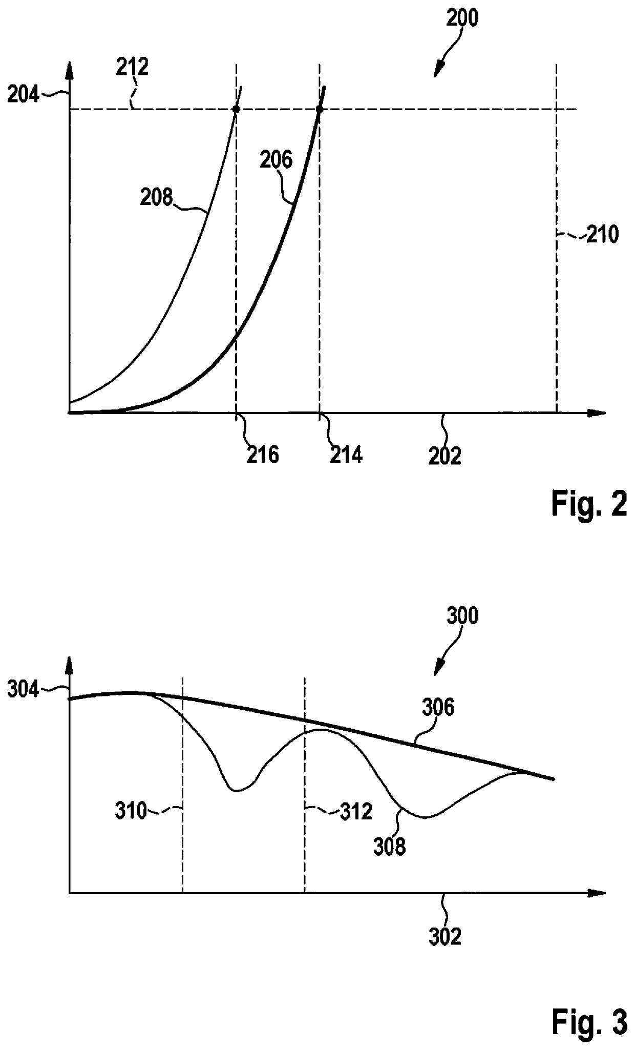
[0027]In diagram 200 of FIG. 2, the volume of working chamber 70 of plunger unit 60 is plotted on X axis 202 and the pressure generated by this plunger unit 60 in one of brake circuits 14, 16 of the power braking system is plotted on Y axis 204. The characteristic curves shown thus indicate pressure / volume characteristic curve 206, 208 of a plunger unit 60 which results when plunger piston 62 is actuated by drive motor 66 in the pressure buildup direction, i.e., in the direction of a shrinking working chamber 70.

[0028]The distance along X axis 202 from Y axis 204 to a vertical line 210 at the right end of diagram 200 illustrates the maximum volume (100%) of working chamber 70 of plunger unit 60, i.e., the volume of working chamber 70 at the beginning of a movement of plunger piston 62 by its drive motor 66.

[0029]A dashed horizontal line 212 at the upper end of diagram 200 indicates a braking intention, or a setpoint brake pressure to be set by plunger unit 60, respectively. This set...


PUM


Abstract

A method for controlling an electronically slip-controllable power braking system of a motor vehicle. Power braking systems are equipped with a plunger unit, which includes a plunger piston accommodated in a plunger cylinder and delimiting a working chamber, for generating brake pressure in brake circuits. This plunger piston is actuatable by an electronically activatable drive in a pressure buildup direction or in the opposing spatial direction thereto in a pressure reducing direction. A time-limited drive of the plunger piston takes place in the pressure reducing direction as soon as an actual brake pressure generated by the plunger unit has reached a predefinable setpoint brake pressure and a decoupling of a wheel brake and the plunger unit from an associated brake circuit has taken place.

Description

CROSS REFERENCE[0001]The present application claims the benefit under 35 U.S.C. § 119 of German Patent Application No. DE 102018208211.1 filed on May 24, 2018, which is expressly incorporated herein by reference in its entirety.FIELD[0002]The present invention is directed to a method for controlling an electronically slip-controllable power braking system.BACKGROUND INFORMATION[0003]Power braking systems are understood hereafter as braking systems in which, under normal operating conditions, i.e., in malfunction-free operation, the brake pressure is not provided by the driver by muscle power, but rather by a pressure generator driven by external power. The drive of the pressure generator takes place as a function of a braking intention, which may be specified, for example, by the driver via an actuating unit of the braking system and / or by an electronic control unit on the basis of existing measurement data of vehicle-side sensor systems.[0004]A conventional electronically slip-cont...

Claims


Application Information

Patent Timeline
Patent Type & Authority Applications(United States)
IPC IPC(8): B60T8/1761B60T13/68B60T8/32B60T8/34B60T8/72
CPCB60T8/17616B60T13/686B60T2240/00B60T8/321B60T8/72B60T2250/04B60T8/34B60T2270/10B60T13/74B60T7/042B60T13/745B60T13/146B60T13/662B60T8/4081
Inventor WAGNER, JENSKRANICH, MATTHIASTAUBITZ, NICHOLASCOLLINS, REIDZAHARIEV, STEFANSTREHLE, ALFRED
Owner ROBERT BOSCH GMBH
Why Eureka
Try Eureka