
Guidepath of carrier vehicle

Active Publication Date: 2019-11-28
HONDA MOTOR CO LTD
View PDF0 Cites 2 Cited by
  • Summary
  • Abstract
  • Description
  • Claims
  • Application Information

AI Technical Summary

Benefits of technology

The present invention aims to provide a guidepath for a carrier vehicle that can prevent misdetection at an intersecting location. By using a magnetism sensor and a restrain tape to suppress diamagnetism, misdetection can be effectively prevented even in cases of deviation in the width direction. This invention is easy to implement and can be used in simple configurations.

Problems solved by technology

In addition, Patent Document 2 describes the problem in that the detection accuracy of a magnetism detection sensor declines in the case of adhering magnetic tape or the like to the groove of an iron plate floor, and in order to solve this problem, configures a magnetic guide body mounting structure by a substrate made of the aforementioned non-magnetic material and the magnetic guide body fitted into a concave groove of the substrate.
However, in either technology, even if it were possible to prevent misdetection at a location where one magnetized guidepath branches, it has been difficult to prevent misdetection at a location where multiple guidepaths intersect.

Method used


Image

  • Guidepath of carrier vehicle
  • Guidepath of carrier vehicle
  • Guidepath of carrier vehicle

Examples


Embodiment Construction

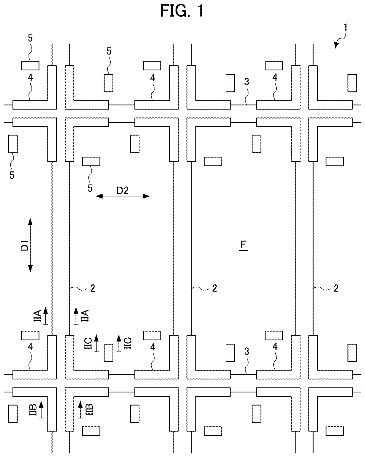
[0027]Hereinafter, an embodiment of the present invention will be explained in detail while referencing the drawings. First, the configuration of a guidepath 1 of a carrier vehicle 10 will be explained using FIGS. 1 and 2. FIG. 1 is a top schematic drawing showing the guidepath 1 of the carrier vehicle 10 according to an embodiment of the present invention.

[0028]As shown in FIG. 1, the guidepath 1 of the carrier vehicle 10 (refer to FIGS. 3 and 4) according to the present invention is arranged on a floor surface F, and guides the carrier vehicle 10 described later (refer to FIGS. 3 and 4). More specifically, the guidepath 1 includes a plurality of magnet guide tapes 2, 3, a plurality of magnetic body tapes 4, and a magnet marker 5.

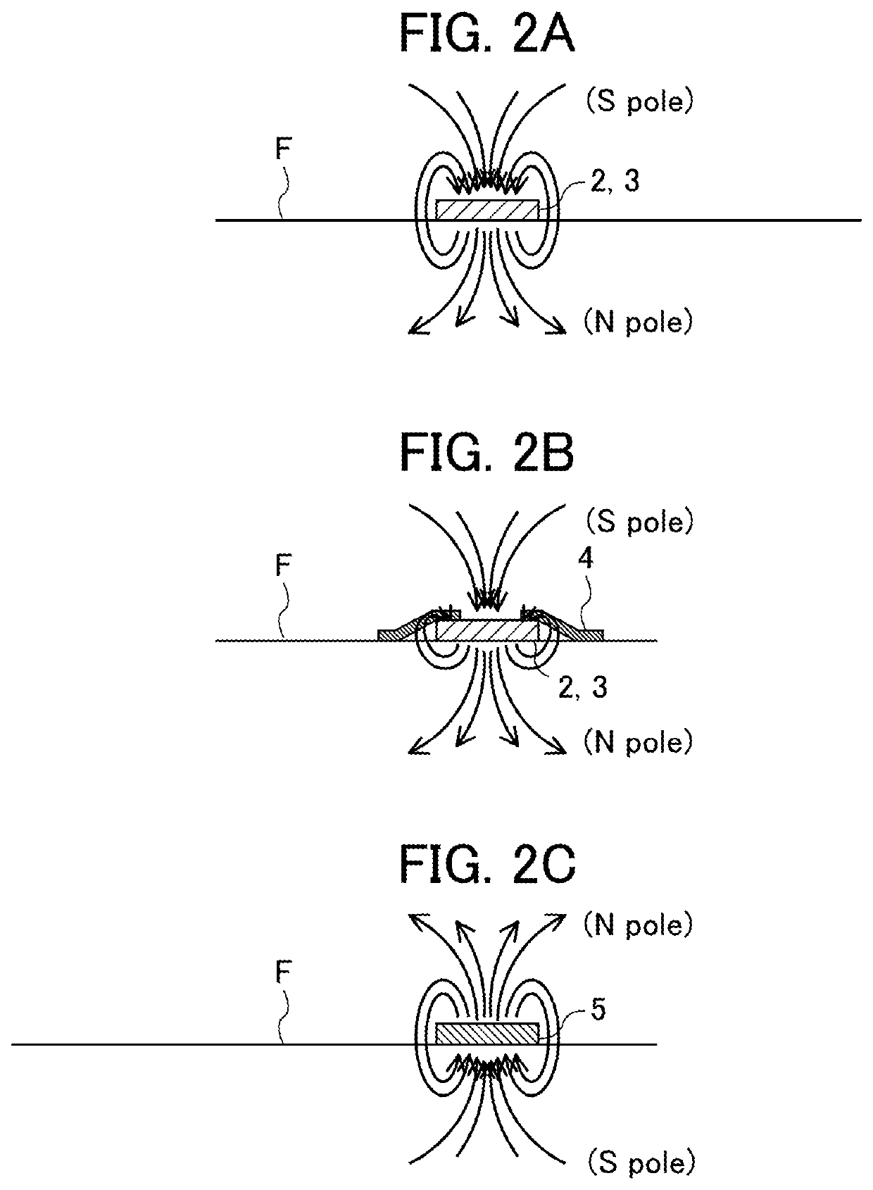
[0029]FIG. 2A is a longitudinal section of the guidepath 1 seen along the arrow IIA-IIA direction in FIG. 1. FIG. 2B is a longitudinal section of the guidepath 1 seen along the arrow IIB-IIB direction in FIG. 1. FIG. 2C is a longitudinal section of the gui...


PUM


Abstract

The guidepath includes: a magnet guide tape which carries S pole, and guides a carrier vehicle in a first direction by the S pole by being arranged on a floor so as to extend in the first direction; a magnet guide tape which carries S pole, and guides the carrier vehicle in a second direction by the S pole by being arranged on the floor so as to extend in a second direction which intersects the first direction; and a magnetic body tape which is arranged at a side of the magnet guide tape at a position above which a marker sensor passes upon the carrier vehicle being guided by the magnet guide tape, and suppresses N pole.

Description

[0001]This application is based on and claims the benefit of priority from Japanese Patent Application No. 2018-097694, filed on 22 May 2018, the content of which is incorporated herein by reference.BACKGROUND OF THE INVENTIONField of the Invention[0002]The present invention relates to a guidepath of a carrier vehicle.Related Art[0003]Conventionally, technology for line trace control of a carrier vehicle using a belt-shaped magnetic body has been known. As documents disclosing this type of technology, there are Patent Documents 1 and 2.[0004]Patent Document 1 describes, with regards to a branching system of an unmanned vehicle which lays a belt-like magnetic body on a route to travel and carries out travel control by detecting this belt-like magnetic body, the matter of defining i and j as positive integers of 2 or more, respectively, installing first to jth belt-like magnetic bodies laid along first to ith branching pathways which branch i number of ways, making left / right branchin...

Claims


Application Information

Patent Timeline
IPC IPC(8): G05D1/02B62D1/28B62D1/26
CPCG05D1/0263G05D1/0265B62D1/283G05D1/0229B62D1/265
Inventor KOBAYASHI, TAKUOFURUNO, TAKUYAOTAKE, YOSHITOGOTO, MASAFUMIOYA, KEISUKEYAMANOBE, TETSURONANBA, NOBUHIRO
Owner HONDA MOTOR CO LTD
Learn More