Electronic device

a technology of electronic devices and components, applied in the field of electronic devices, can solve problems such as complex structur

Active Publication Date: 2019-11-28
PANASONIC INTELLECTUAL PROPERTY MANAGEMENT CO LTD
View PDF0 Cites 5 Cited by
  • Summary
  • Abstract
  • Description
  • Claims
  • Application Information

AI Technical Summary

Benefits of technology

[0005]The present disclosure provides an electronic device having a lock mechanism that has a small number of parts and a simple structure.
[0010]With the technique of the present disclosure, a number of parts is reduced, and a structure is simplified. As a result, strength of the parts themselves can be improved, and solidity can be enhanced.

Problems solved by technology

Furthermore, this engagement mechanism has many parts such as a plurality of springs, a plurality of lock pawls, and a lock case, and has a complicated structure.

Method used


Image

  • Electronic device
  • Electronic device
  • Electronic device

Examples


first exemplary embodiment

[0030]A first exemplary embodiment will be described below with reference to the drawings.

[1. Configuration]

[1-1. Outline]

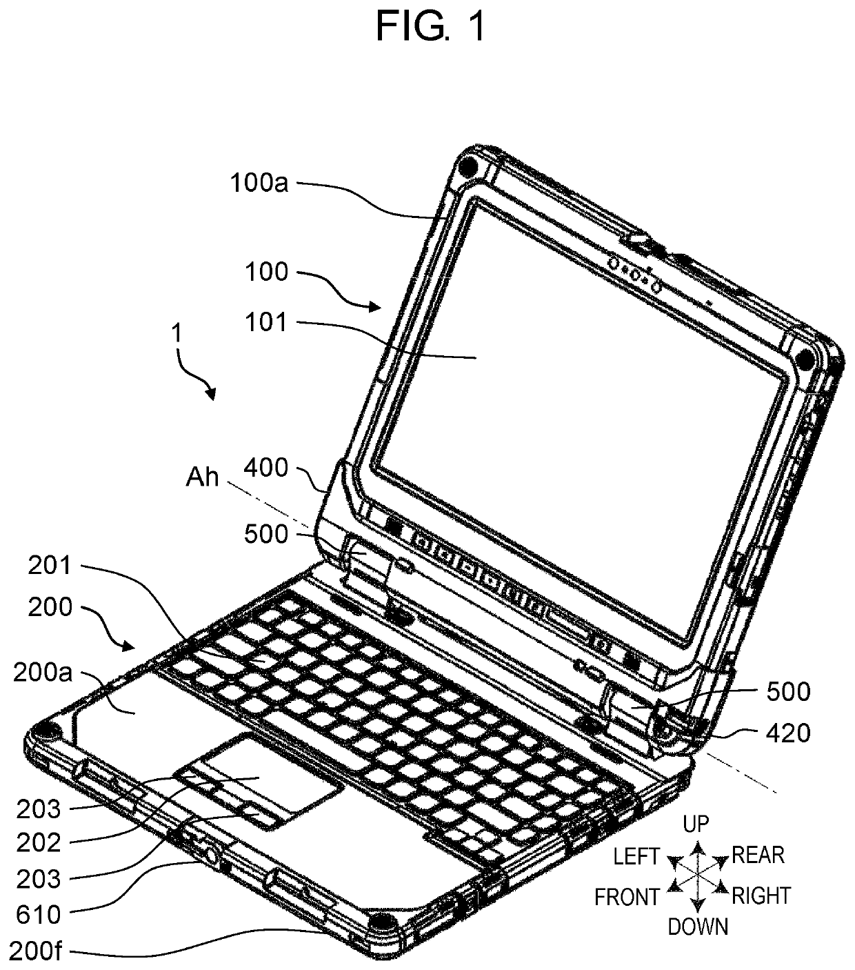
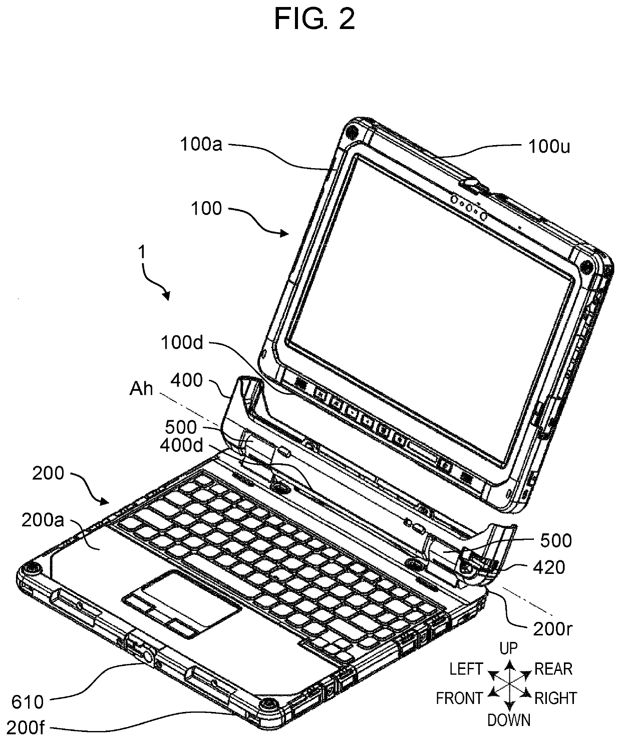
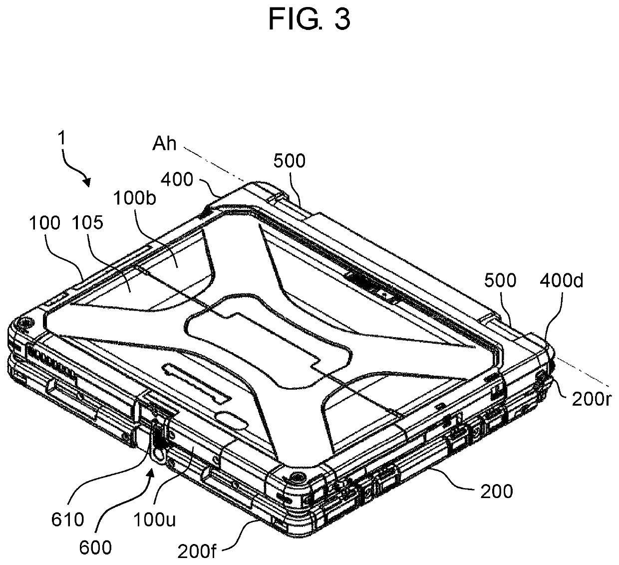
[0031]FIGS. 1, 2, and 3 are perspective views of a computer according to the first exemplary embodiment. FIG. 1 illustrates a state in which tablet unit 100 is attached to keyboard unit 200. FIG. 2 illustrates a state in which tablet unit 100 is detached from keyboard unit 200. FIG. 3 illustrates a state in which tablet unit 100 is closed. In the drawings, directions are given as appropriate for convenience for the purpose of explanation and easier understanding. The directions are based on directions viewed by a user when computer 1 is utilized in a general utilization mode, but it is not intended that computer 1 should be used and disposed in these directions. In FIGS. 1 and 2, a left-right direction corresponds to a device width direction of tablet unit 100 and keyboard unit 200. Further, an up-down direction substantially corresponds to a device depth directi...


PUM


Abstract

An electronic device includes a first unit, a second unit, and a lock mechanism. The lock mechanism includes: an engagement projection provided on a third side surface of the first unit; a latch provided on a fourth side surface of the second unit, the latch being rotatable around a rotation axis provided perpendicular to the fourth side surface between a first rotational position where the latch does not engage with the engagement projection and a second rotational position where the latch is engageable with the engagement projection, and an urging member that urges the latch to be positioned at the second rotational position. The latch has an inclined part. When the latch is located at the second rotational position and the first unit is changed to a closed state from a state where the first unit is not closed, the inclined part abuts on the engagement projection during the change.

Description

BACKGROUND1. Technical Field[0001]The present disclosure relates to an electronic device having a lock mechanism that locks a first unit in a second unit.2. Description of the Related Art[0002]PTL 1 discloses an information processing device having a lock mechanism that locks a body unit and a display unit coupled to each other via hinges in a closed state.[0003]Here, PTL 1 is Unexamined Japanese Patent Publication No. 2004-326440.SUMMARY[0004]In an information processing device of PTL 1, a mechanism part in the display unit needs to be rotatable. Further, it is necessary to provide, in the body unit, an engagement mechanism that engages projection pieces of a mechanism in the display unit. Furthermore, this engagement mechanism has many parts such as a plurality of springs, a plurality of lock pawls, and a lock case, and has a complicated structure.[0005]The present disclosure provides an electronic device having a lock mechanism that has a small number of parts and a simple struct...

Claims


Application Information

Patent Timeline
Patent Type & Authority Applications(United States)
IPC IPC(8): G06F1/16H05K5/03E05B63/24E05B65/00
CPCG06F1/1679E05B63/24E05B65/006G06F1/1616H05K5/03G06F1/1654G06F1/1656G06F2200/1633E05B65/0067E05B15/0053E05C3/04
Inventor URIMOTO, TETSUYA
Owner PANASONIC INTELLECTUAL PROPERTY MANAGEMENT CO LTD
Why Eureka
Try Eureka