
Electromechanical Switching Device Utilizing Contacts on Aluminum Conductors and Method of Adhesion

Active Publication Date: 2019-11-28
SAFRAN ELECTRICAL & POWER
View PDF0 Cites 0 Cited by
  • Summary
  • Abstract
  • Description
  • Claims
  • Application Information

AI Technical Summary

Benefits of technology

The patent describes an electrical switching device with a movable contact assembly that can connect or disconnect two static contact assemblies. The device includes a spring to keep the contact assembly in the disengaged position when not in use. The contacts are made of silver and aluminum and are welded onto substrates using a process called percussion welding. The method includes using a projection to focus the arc during welding. The technical effect of this device is the ability to create a reliable electrical connection that can be easily controlled and disconnected.

Problems solved by technology

These switching devices typically utilize copper, which is a relatively dense material and thus, at a particular size, the copper portion of the switching device has a relatively high mass that unnecessarily increases the overall mass of the switching device.

Method used


Image

  • Electromechanical Switching Device Utilizing Contacts on Aluminum Conductors and Method of Adhesion
  • Electromechanical Switching Device Utilizing Contacts on Aluminum Conductors and Method of Adhesion
  • Electromechanical Switching Device Utilizing Contacts on Aluminum Conductors and Method of Adhesion

Examples


Embodiment Construction

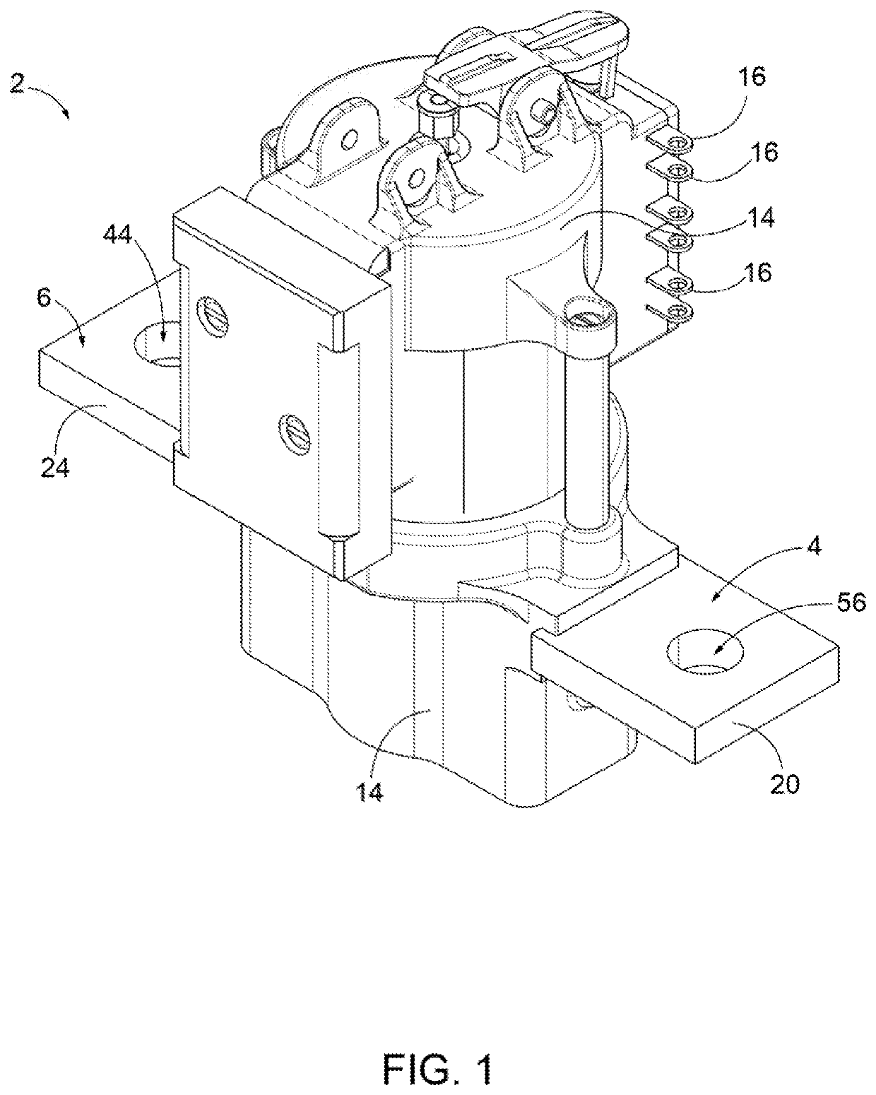
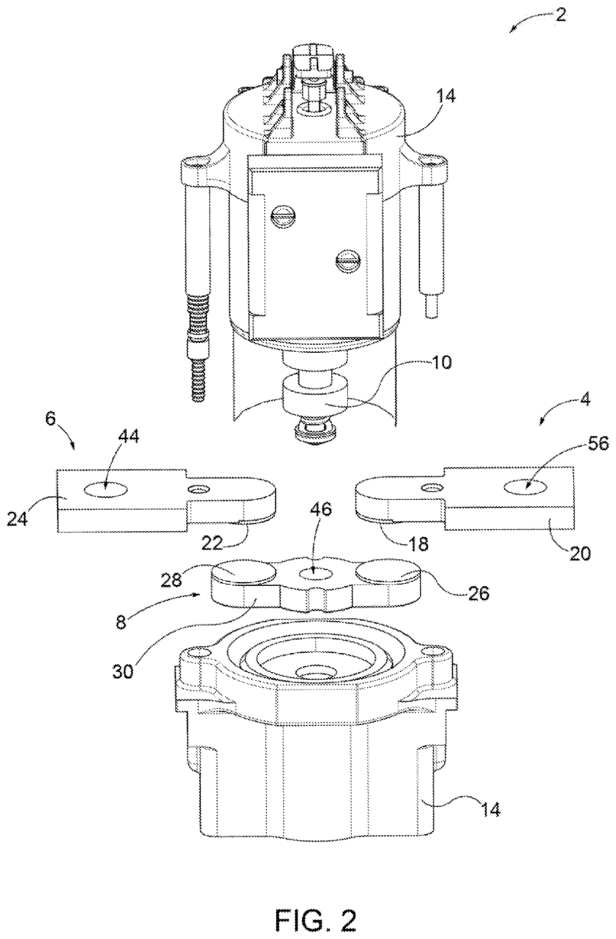
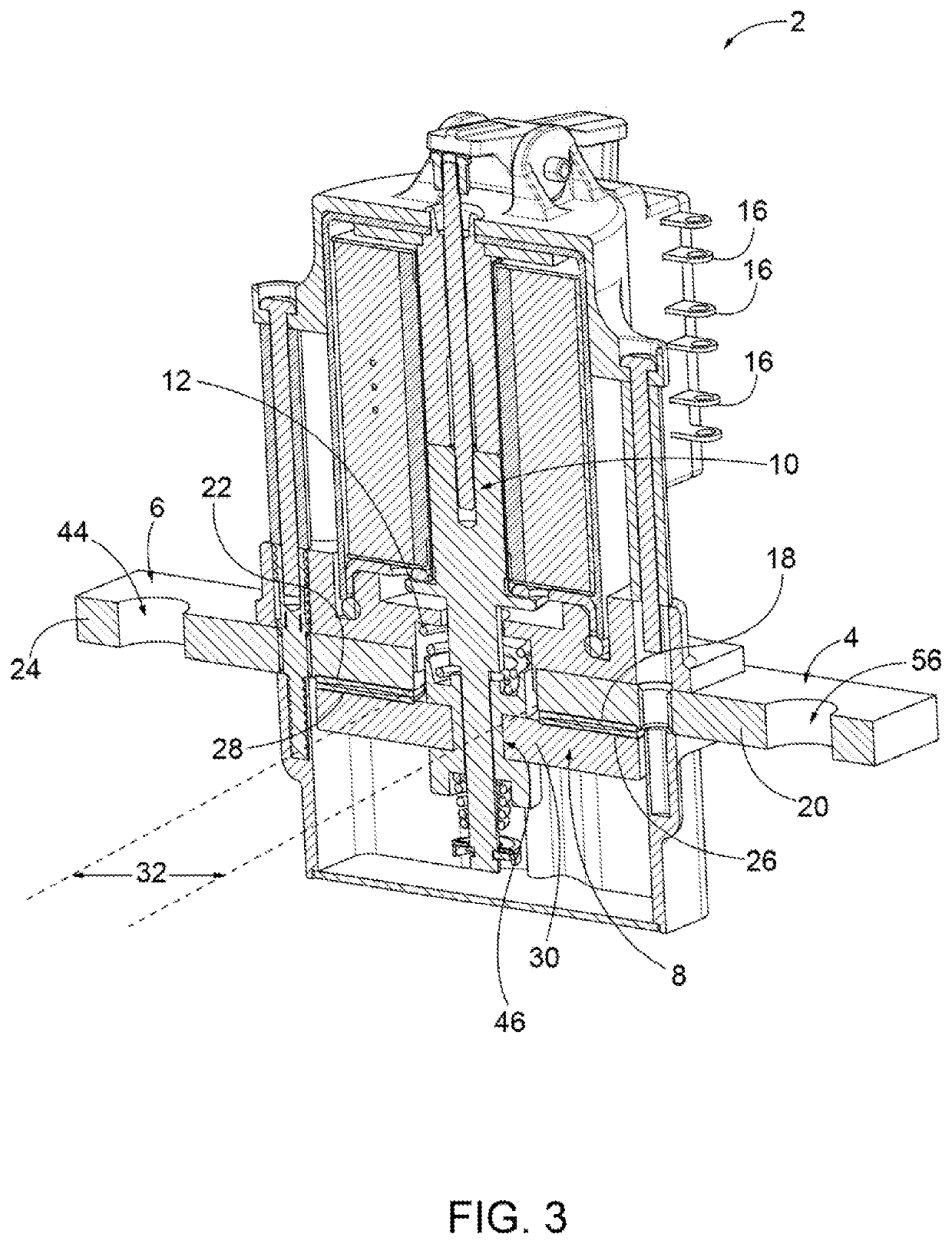
[0011]Referring to the figures, there is shown an electrical switching device 2 for making and breaking a flow of current through a circuit and for use is aerospace applications. The electrical switching device 2 includes a first static contact assembly 4, a second static contact assembly 6, and a movable contact assembly 8. The first and second static contact assemblies 4, 6 are arranged in the switching device 2 at static (i.e. fixed) locations and are immobilized relative to a structure 14 for housing the various components of the electrical switching device 2. The movable contact assembly 8 is movably mounted in the electrical switching device 2, and is movable relative to the structure 14 between an engaged position (FIG. 3) and a disengaged position (FIG. 4).

[0012]When in the engaged position, the movable contact assembly 8 makes an electrical connection between the first and second static contact assemblies 4, 6 by contacting both of the first and second static contact assemb...


PUM

PropertyMeasurementUnit
Diameteraaaaaaaaaa
Adhesion strengthaaaaaaaaaa

Abstract

An electrical switching device and related methods, for use in aerospace applications include a first static contact assembly, a second static contact assembly, a movable contact assembly for making an electrical connection between the first and second static contact assemblies. The first contact assembly, the second contact assembly and the movable contact assembly each include a silver contact that is percussion welded to the aluminum substrate. Before percussion welding, the silver contact includes a projection for focusing an arc during percussion welding.

Description

BACKGROUND[0001]Aerospace switching devices include contacts to make and break electrical connections. These switching devices typically utilize copper, which is a relatively dense material and thus, at a particular size, the copper portion of the switching device has a relatively high mass that unnecessarily increases the overall mass of the switching device.BRIEF DESCRIPTION[0002]According to one aspect, an electrical switching device includes a first static contact assembly, a second static contact assembly arranged relative to the first static contact assembly such that first and second contact assemblies are separated by a gap, a movable contact assembly for making an electrical connection between the first and second static contact assemblies, an activator that when actuated, moves the movable contact assembly to make the electrical connection between the first and second static contact assemblies, and a spring biasing the movable contact assembly in a direction away from at l...

Claims


Application Information

Patent Timeline
IPC IPC(8): H01H33/08
CPCH01H11/043H01H50/546B23K9/22B23K9/232B23K2103/10B23K2103/12H01H33/08H01H2205/002
Inventor GEIER, DAVID MICHAELMAKA, OLIVIER
Owner SAFRAN ELECTRICAL & POWER
Features
  • Generate Ideas
  • Intellectual Property
  • Life Sciences
  • Materials
  • Tech Scout
  • Unparalleled Data Quality
  • Higher Quality Content
  • 60% Fewer Hallucinations
Learn More