
Vibrator

a vibrator and rotating shaft technology, applied in the field of vibrators, can solve the problems of large vibration, small vibration, and large and achieve the effects of reducing the thickness of the vibrator in the axial direction, reducing the shape of the vibrator, and stabilizing the operation

Active Publication Date: 2019-12-05
ONKYO KK
View PDF8 Cites 4 Cited by
  • Summary
  • Abstract
  • Description
  • Claims
  • Application Information

AI Technical Summary

Benefits of technology

The present invention provides a vibrator that uses a coiled wave spring and a magnetic circuit. The coiled wave spring is configured such that the steel wire is multiple-wound in the spiral shape to alternately form peak and trough portions, which contact each other in the axial direction. This design allows the vibrator to provide stable operation even in a case where the magnetic circuit is greatly displaced. The vibrator also includes a yoke with a flange portion that can be fixed to the coiled wave spring or the retaining ring member, providing a smaller size and cost-effectiveness of the vibrator in comparison to conventional designs. Overall, the present invention allows for a small-sized vibrator that provides great vibration.

Problems solved by technology

As a result, there is a problem that the entirety of the vibrator tends to be large as compared to the size of the magnetic circuit.
On the other hand, a small vibrator has a problem that a magnetic circuit is relatively small, and as a result, vibration tends to be small.
Further, the damper or the suspension of the vibrator has a problem that a load on the cantilever-shaped flat arm member specifically called a butterfly damper increases in term of strength as the amount of displacement in a vibration direction increases and such an arm member is easily ruptured due to weakness in a direction perpendicular to the vibration direction in terms of strength.

Method used


Image

  • Vibrator
  • Vibrator
  • Vibrator

Examples


first embodiment

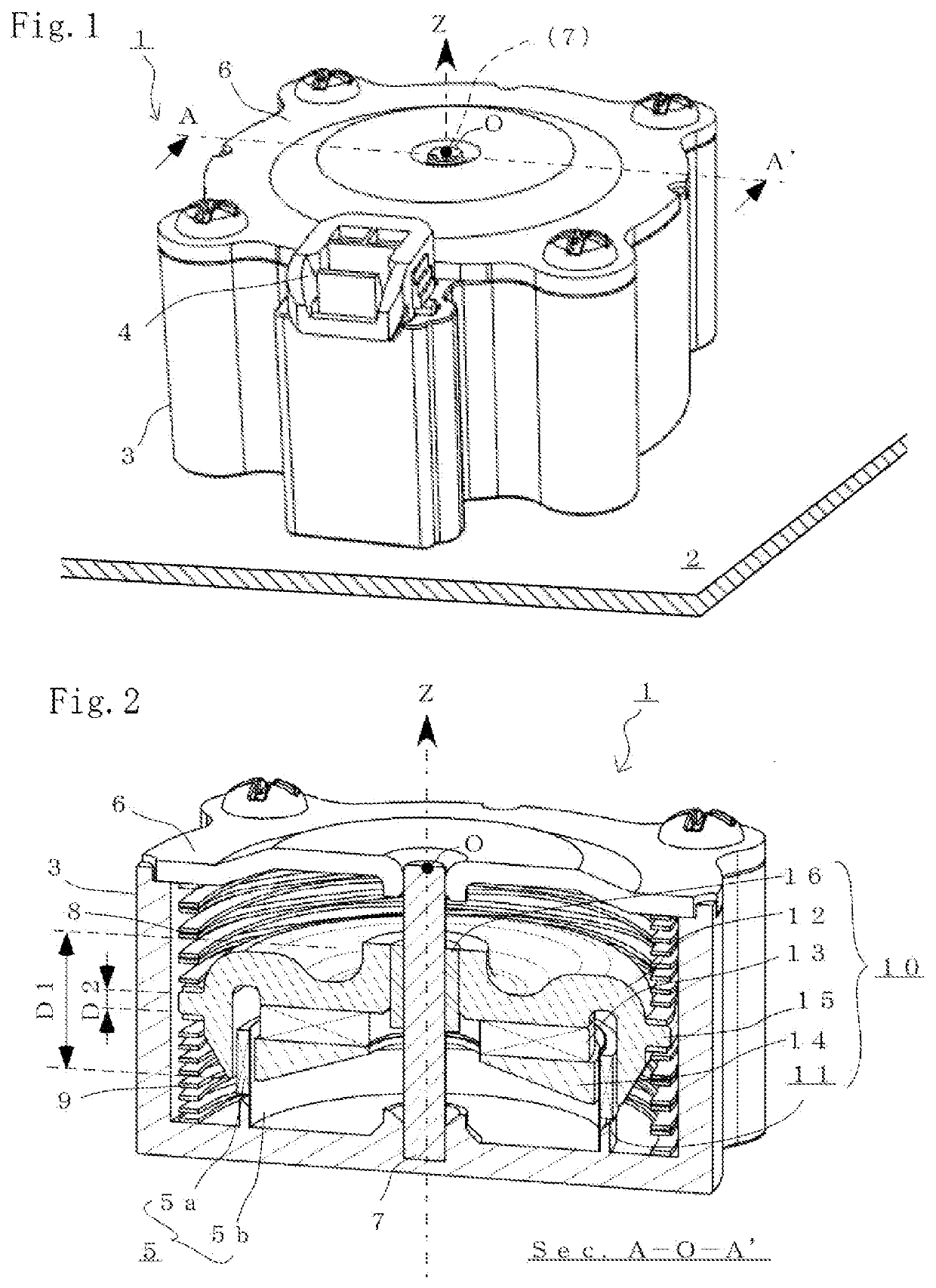
[0035]FIGS. 1 and 2 are views for describing a vibrator 1 according to a preferred embodiment of the present invention. Specifically, FIG. 1 is a perspective view of the vibrator 1 attached to a flat plate 2 as an attachment target member. Moreover, FIG. 2 is a sectional view of an internal structure of the vibrator 1 in an A-O-A′ section of FIG. 1. Note that some configurations unnecessary for description of the present invention are not shown in the figures and are not described. Needless to say, the form of the vibrator 1 is not limited to the case of the present embodiment.

[0036]The vibrator 1 of the present embodiment is an electrodynamic vibrator including a frame 3 and a flange member 6 defining an entire shape and including an internal magnet type magnetic circuit 10 in a substantially cylindrical internal space. The vibrator 1 is attached to the flat plate 2 so that the flat plate 2 can vibrate to emit a sound wave. The vibrator 1 having a terminal 4 to which audio signal c...

second embodiment

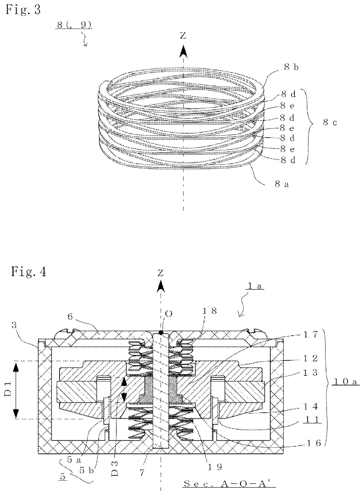
[0067]FIG. 4 is a view for describing a vibrator 1a according to another preferred embodiment of the present invention. Specifically, FIG. 4 is a sectional view of an internal structure of the vibrator 1a in an A-O-A′ section similar to that of FIG. 2. Note that as in the case of the above-described embodiment, the same reference numerals are used to represent some configurations unnecessary for description of the present invention, and these configurations are not shown in the figure and are not described. Needless to say, the form of the vibrator 1a is not limited to the case of the present embodiment.

[0068]The vibrator 1a of the present embodiment is an electrodynamic vibrator having a substantially cylindrical entire shape and including a larger voice coil 5 as compared to the case of the previous embodiment and an external magnet type magnetic circuit 10a. Thus, the vibrator 1a is configured such that a coiled wave spring 8, 9 is not fixed to the flange portion 15 provided on t...

third embodiment

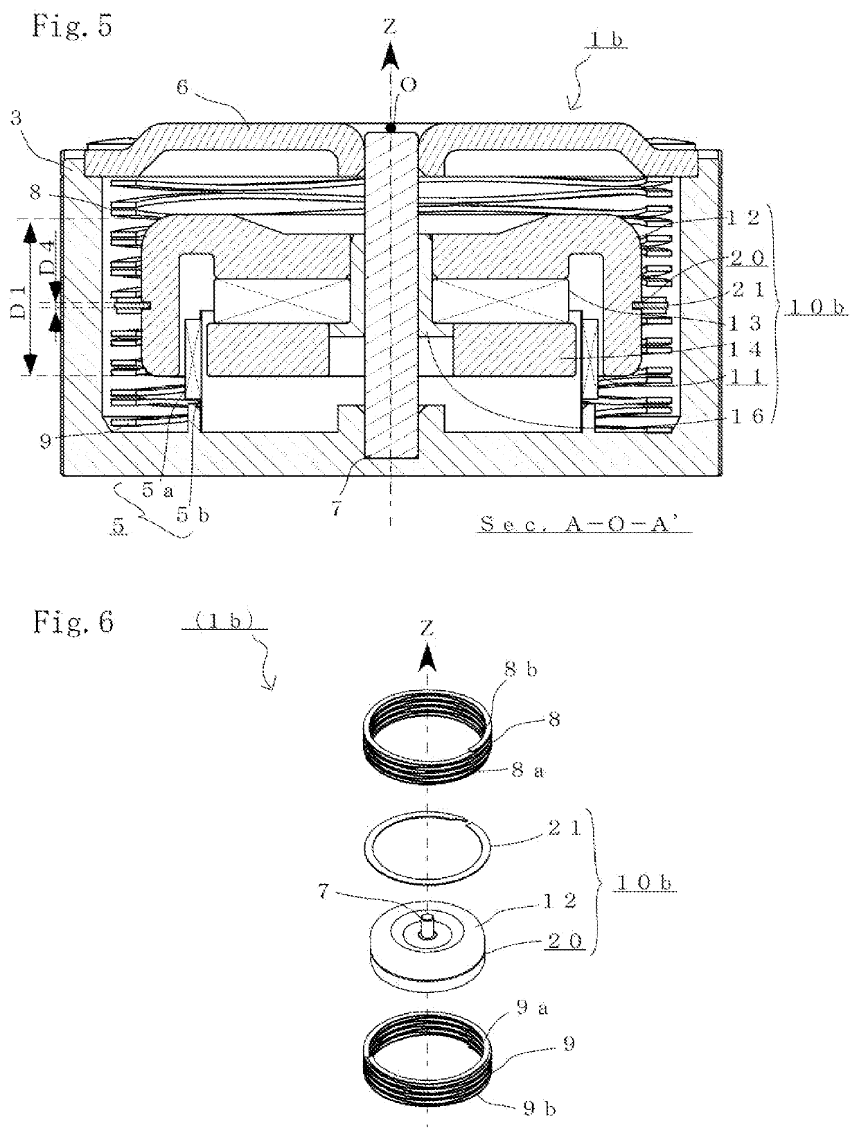
[0077]FIGS. 5 and 6 are views for describing a vibrator 1b according to still another embodiment of the present invention. Specifically, FIG. 5 is a sectional view of an internal structure of the vibrator in an A-O-A′ section similar to that of FIG. 2, and FIG. 6 is an exploded perspective view illustrating only a shaft member 7, coiled wave springs 8, 9, and a magnetic circuit 10b arranged inside a frame. Note that as in the cases of the above-described embodiments, the same reference numerals are used to represent some configurations unnecessary for description of the present invention, and these configurations are not shown in the figures and are not described. Needless to say, the form of the vibrator 1b is not limited to the case of the present embodiment.

[0078]The vibrator 1b is an electrodynamic vibrator having a substantially cylindrical entire shape and including the internal magnet type magnetic circuit 10b as in the vibrator 1 of the previous embodiment. Note that the vib...


PUM


Abstract

The vibrator includes a frame defining an internal space, a voice coil fixed to the frame in the internal space, a shaft member arranged along an axial direction of the coil in the internal space, a magnetic circuit arranged slidably relative to the shaft member and having a magnetic gap in which the coil is arranged, and a compression coil spring arranged between one end side of the magnetic circuit and one end side of the frame along the axial direction in the internal space. The compression coil spring is a coiled wave spring configured such that a plate-shaped steel wire is multiple-wound in a spiral shape in a circumferential direction of the shaft member to alternately form a peak portion and a trough portion at an equal interval and the peak portion and the trough portion contact each other in the axial direction.

Description

BACKGROUND OF THE INVENTION1. Field of the Invention[0001]The present invention relates to a vibrator configured to convert an electric audio signal into vibration and attached to an attachment target member to vibrate the attachment target member to transmit vibration or emit a sound wave. Specifically, the present invention relates to a vibrator configured to provide, even though the vibrator is small, great vibration and provide stable operation.2. Description of the Related Art[0002]A vibrator is attached to an attachment target member to vibrate the attachment target member, thereby transmitting vibration and emitting a sound wave. An electrodynamic vibrator includes, for converting an electric audio signal into vibration, a magnetic circuit having a magnetic gap where a voice coil is arranged. Typically, in a vibrator configured to vibrate a magnetic circuit including a magnet, the magnetic circuit supported by a damper reciprocates and vibrates in a single given axial directi...

Claims


Application Information

Patent Timeline
Patent Type & Authority Applications(United States)
IPC IPC(8): B06B1/04H02K33/16F16F1/32
CPCF16F1/328B06B1/045H02K33/16
Inventor YOSHIMURA, HAJIME
Owner ONKYO KK
Learn More