Optical imaging system

a technology of optical imaging and lens arrangement, applied in the field of optical imaging system, can solve problems such as difficulty in arranging lenses in the camera modul

Active Publication Date: 2019-12-05
SAMSUNG ELECTRO MECHANICS CO LTD
View PDF0 Cites 11 Cited by
  • Summary
  • Abstract
  • Description
  • Claims
  • Application Information

AI Technical Summary

Benefits of technology

[0006]This Summary is provided to introduce a selection of concepts in a simplified form that are further described below in the Detailed Description. This Summary is not inten

Problems solved by technology

However, since the mobile communications terminal in which the camera module is mounted t

Method used


Image

  • Optical imaging system
  • Optical imaging system
  • Optical imaging system

Examples


first example

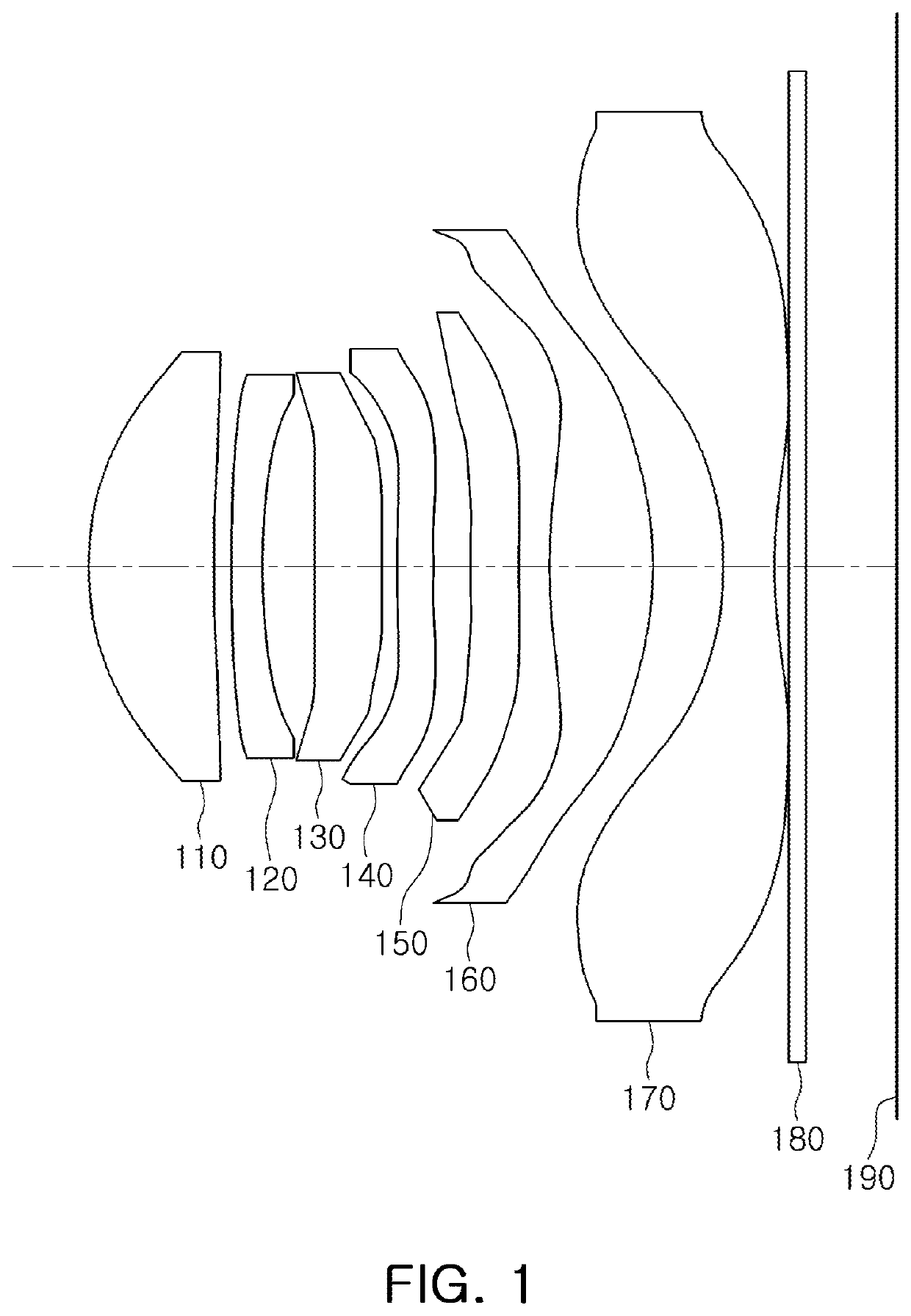
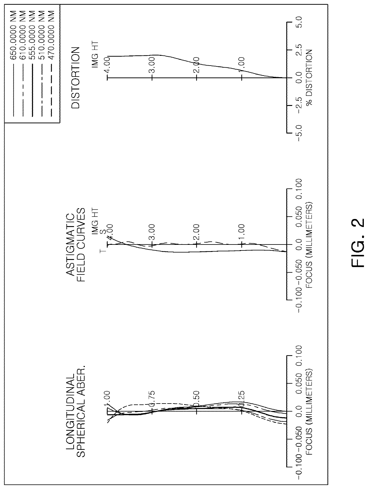
[0197]FIG. 1 is a view illustrating a first example of an optical imaging system, and FIG. 2 illustrates aberration curves of the optical imaging system of FIG. 1.

[0198]The first example of the optical imaging system includes a first lens 110, a second lens 120, a third lens 130, a fourth lens 140, a fifth lens 150, a sixth lens 160, a seventh lens 170, a filter 180, an image sensor 190, and a stop (not shown) disposed between the first lens 110 and the second lens 120.

[0199]The first lens 110 has a positive refractive power, a paraxial region of an object-side surface thereof is convex, and a paraxial region of an image-side surface thereof is concave.

[0200]The second lens 120 has a negative refractive power, a paraxial region of an object-side surface thereof is convex, and a paraxial region of an image-side surface thereof is concave.

[0201]The third lens 130 has a positive refractive power, and a paraxial region of each of an object-side surface and an image-side surface thereof ...

second example

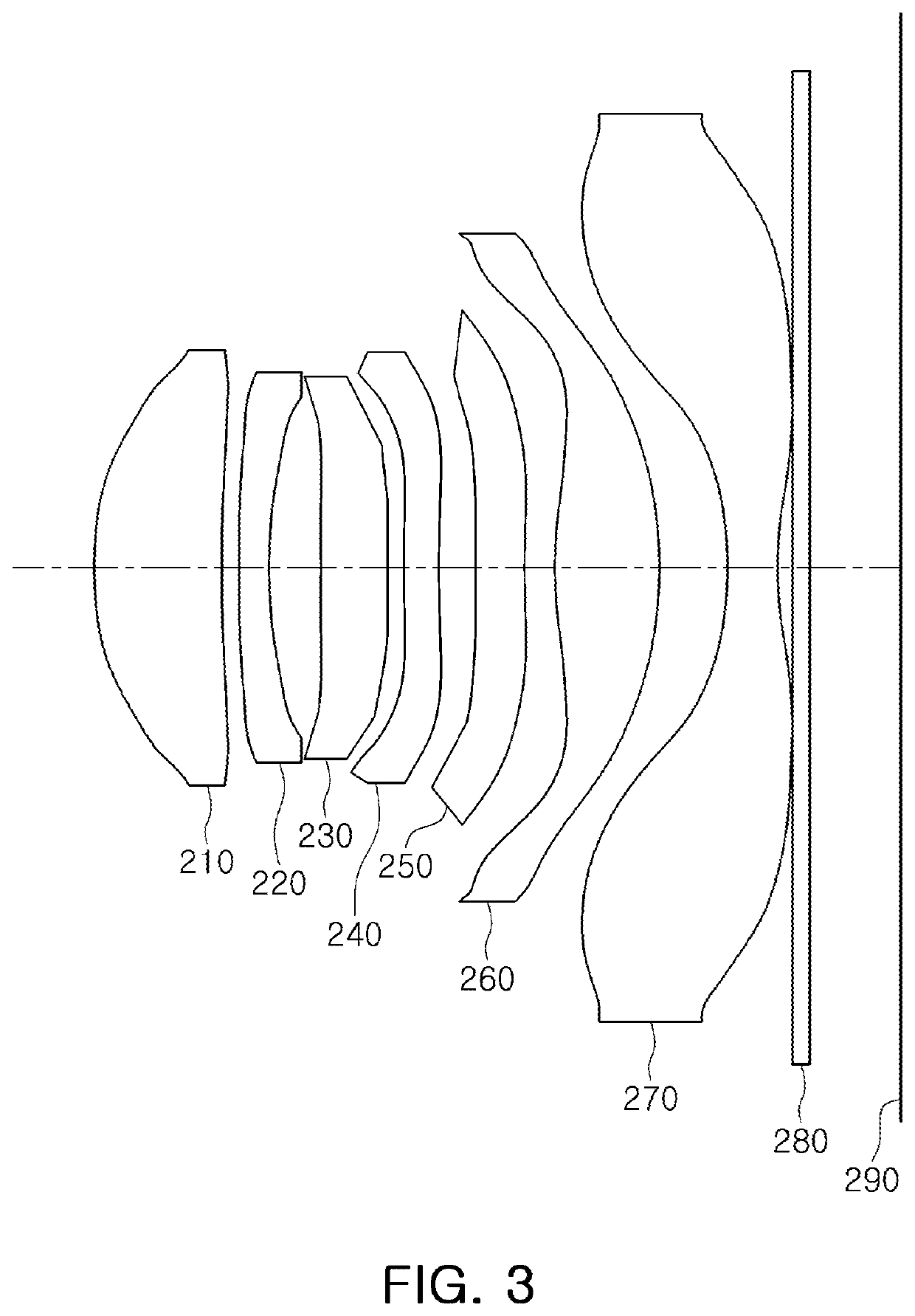
[0210]FIG. 3 is a view illustrating a second example of an optical imaging system, and FIG. 4 illustrates aberration curves of the optical imaging system of FIG. 3.

[0211]The second example of the optical imaging system includes a first lens 210, a second lens 220, a third lens 230, a fourth lens 240, a fifth lens 250, a sixth lens 260, a seventh lens 270, a filter 280, an image sensor 290, and a stop (not shown) disposed between the first lens 210 and the second lens 220.

[0212]The first lens 210 has a positive refractive power, a paraxial region of an object-side surface thereof is convex, and a paraxial region of an image-side surface thereof is concave.

[0213]The second lens 220 has a negative refractive power, a paraxial region of an object-side surface thereof is convex, and a paraxial region of an image-side surface thereof is concave.

[0214]The third lens 230 has a positive refractive power, and a paraxial region of each of an object-side surface and an image-side surface thereo...

third example

[0223]FIG. 5 is a view illustrating a third example of an optical imaging system, and FIG. 6 illustrates aberration curves of the optical imaging system of FIG. 5.

[0224]The third example of the optical imaging system includes a first lens 310, a second lens 320, a third lens 330, a fourth lens 340, a fifth lens 350, a sixth lens 360, a seventh lens 370, a filter 380, an image sensor 390, and a stop (not shown) disposed between the second lens 320 and the third lens 330.

[0225]The first lens 310 has a positive refractive power, a paraxial region of an object-side surface thereof is convex, and a paraxial region of an image-side surface thereof is concave.

[0226]The second lens 320 has a negative refractive power, a paraxial region of an object-side surface thereof is convex, and a paraxial region of an image-side surface thereof is concave.

[0227]The third lens 330 has a positive refractive power, a paraxial region of an object-side surface thereof is convex, and a paraxial region of an...


PUM


Abstract

An optical imaging system includes a first lens, a second lens, a third lens, a fourth lens, a fifth lens, a sixth lens, and a seventh lens sequentially disposed in numerical order along an optical axis of the optical imaging system from an object side of the optical imaging system toward an imaging plane of the optical imaging system, wherein the first to seventh lenses are spaced apart from each other along the optical axis, and the optical imaging system satisfies 0.4<L1TR/L7TR<1.9, where L1TR is an overall outer diameter of the first lens, L7TR is an overall outer diameter of the seventh lens, and L1TR and L7TR are expressed in a same unit of measurement.

Description

CROSS-REFERENCE TO RELATED APPLICATIONS[0001]This application claims the benefit under 35 USC 119(a) of Korean Patent Application Nos. 10-2018-0061410 filed on May 29, 2018, and 10-2018-0106171 filed on Sep. 5, 2018, in the Korean Intellectual Property Office, the entire disclosures of which are incorporated herein by reference for all purposes.BACKGROUND1. Field[0002]This application relates to an optical imaging system.2. Description of Related Art[0003]Recently, mobile communications terminals have been provided with camera modules, enabling video calling and image capturing. In addition, as utilization of the camera modules mounted in the mobile communications terminals has increased, camera modules for the mobile communications terminals have gradually been required to have high resolution and performance.[0004]Therefore, the number of lenses included in the camera module has increased. However, since the mobile communications terminal in which the camera module is mounted tend...

Claims


Application Information

Patent Timeline
IPC IPC(8): G02B13/00G02B9/64G02B7/02G03B30/00
CPCG02B9/64G02B13/0045G02B13/0015G02B7/021G02B7/022
Inventor KIM, HAG CHULLEE, EUN CHONGJO, YONG JOOAN, GA YOUNG
Owner SAMSUNG ELECTRO MECHANICS CO LTD
Why Eureka
Try Eureka