LED arrangement with over-current protection

a technology of overcurrent protection and led arrangement, which is applied in the direction of electroluminescent light source, electrical lighting source, and use of semiconductor lamps, etc., can solve the problems of high temperature, fire risk, safety issues, etc., and achieve faster response time, faster or even predictive approach, and more accurate sensing

Active Publication Date: 2019-12-05
SIGNIFY HLDG BV
View PDF1 Cites 0 Cited by
  • Summary
  • Abstract
  • Description
  • Claims
  • Application Information

AI Technical Summary

Benefits of technology

[0024]This arrangement provides current sensing locally on the LED board, so that a safety cut-off may be implemented. Current protection enables more accurate sensing and it can be detected before any risk, whereas temperature sensing has a slower response time. Excessive current is the most likely cause of increased temperatures, so that over-current protection may also function as a more rapid or even predictive approach for providing temperature protection.
[0025]The protection trigger point for the LED arrangement current can be precisely set. By using a series switch, the protection can be triggered and released unlimited times. The circuit components may all be implemented as low cost surface mount semiconductor components, which have long life. During normal operation, the protection circuit elements may be configured to consume very low power, thereby maintaining a high system efficiency.
[0026]The switch control circuit may comprise a reference voltage unit and a comparison circuit for comparing the current sensor signal with a voltage reference set by the reference voltage unit. This enables a simple voltage comparison to be used for the over-current detection.

Problems solved by technology

When a driver is configurable, there may be safety issues resulting from the particular LED PCB boards that the driver is used to drive.
The LEDs will be over-driven, and the over-current in the LEDs can cause high temperatures and even present a fire risk.
If a resistor is used for the current setting configuration, the resistor can become open circuit, or become disconnected, thus causing potential over-current issues or over-heating.
This is a critical safety issue.
If the wires or cable are broken, the protection is lost.
In an application with multiple LED boards, each LED board has a temperature sensor, and this complicates the connection.
The wires or cables and their connections also increase cost of the fixture.
When a thermal fuse is triggered, the LED board is damaged, and has to be replaced, which increases the installation cost.
Another drawback of a thermal fuse is that it has a high internal resistance.
In normal applications, it consumes power which causes a reduced system efficiency.
This however increases the size and cost and may not be easy to mount on the LED board.
These thermal protection systems are slow to respond, and may only respond after there has been damage to the LED board.

Method used


Image

  • LED arrangement with over-current protection
  • LED arrangement with over-current protection
  • LED arrangement with over-current protection

Examples


Embodiment Construction

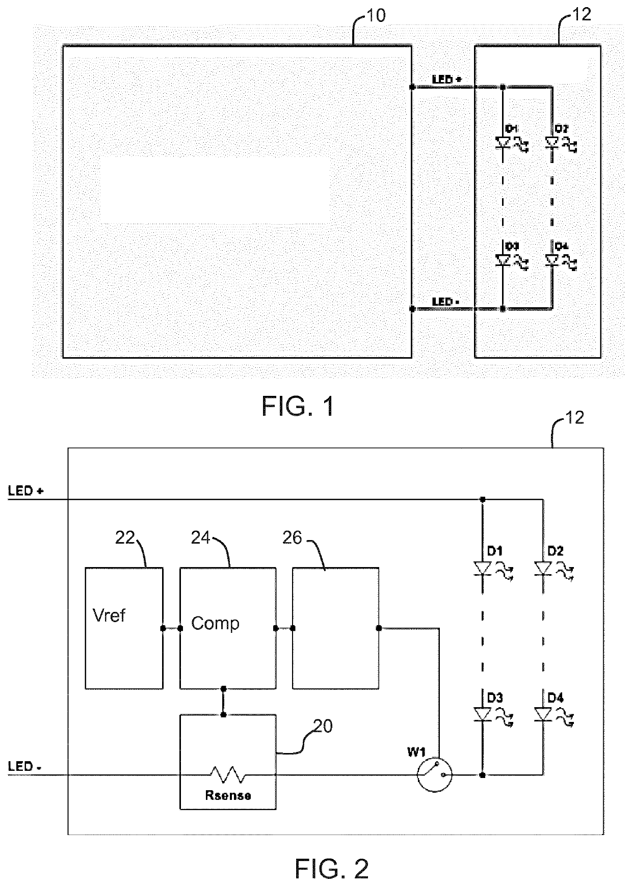
[0053]The invention provides an LED board which comprises an arrangement of LEDs, a current sensor for sensing a current flowing through the arrangement of LEDs and a cut-off switch in series with the arrangement of LEDs. The cut-off switch is controlled in dependence on the sensed current. In this way, over-current protection is provided at the LED board level, without needing any signal communication between the LED board and the LED driver.

[0054]FIG. 1 shows a typical LED lighting fixture in which a configurable LED driver 10 drives an LED board 12. Together they form a luminaire. On the LED board 12, there are multiple LEDs are connected in parallel and / or in series. FIG. 1 shows a set of parallel LED strings, represented by diodes D1. D2, D3 and D4.

[0055]The LED driver 10 provides correct current to the LED boards. The LED driver 10 is configurable so that it can operate at different current settings for different LED arrangements. If the output current is programmed with wrong...


PUM


Abstract

An LED board comprises an arrangement of LEDs, a current sensor for sensing a current flowing through the arrangement of LEDs and a cut-off switch in series with the arrangement of LEDs. The cut-off switch is controlled in dependence on the sensed current. In this way, over-current protection is provided at the LED board level, without needing any signal communication between the LED board and the LED driver.

Description

FIELD OF THE INVENTION[0001]This invention relates to LED arrangements, and relates in particular to the provision of over-current protection.BACKGROUND OF THE INVENTION[0002]An LED lighting fixture typically consists of LED drivers and LEDs on PCB boards. The LEDs are connected in series or parallel, or in a network of series and parallel connections.[0003]To make sure the LEDs output the correct lighting level and have a long lifetime, the correct current needs to be provided to the LEDs. For a given fixture, the number of LEDs and LED type are fixed, and the current rating is also fixed.[0004]US2011 / 0109231 shows an example of LED current control wherein the LED current control circuit is adapted to the LED module. US2011 / 0109231 discloses a regulation and a protection of the LED module which is made on the LED driver side.[0005]US2012 / 0223644 shows a LED driving circuit providing current to a LED module that fit together. US2012 / 0223664 discloses current protection and regulatio...

Claims


Application Information

Patent Timeline
Patent Type & Authority Applications(United States)
IPC IPC(8): H05B33/08H05B44/00H05B45/50
CPCH05B33/089Y02B20/30H05B45/56H05B47/25H05B45/50
Inventor FANG, YUHONGMENDOZA, ERNESTOSHROTRIYA, AMEYA DILIP
Owner SIGNIFY HLDG BV
Why Eureka
Try Eureka