Apparatus for making a spunbond web from filaments

a technology of filaments and apparatus, which is applied in the field of apparatus for making a spunbond web from filaments, can solve the problems of inhomogeneity of diameters in deposited filaments, poor strength of spunbond webs, and negatively affecting the homogeneity of spunbond webs, etc., and achieves low titre, high strength, and excellent homogeneity.

Active Publication Date: 2019-12-12
REFENHAEUSER GMBH & CO KG MASCHFAB
View PDF0 Cites 1 Cited by
  • Summary
  • Abstract
  • Description
  • Claims
  • Application Information

AI Technical Summary

Benefits of technology

[0004]In contrast, the object of the invention is to provide an apparatus of the aforementioned type with which the disadvantages described above can be avoided in an effective and functionally safe manner.
[0025]The invention is based on the recognition that spunbond of optimal homogeneity can be produced using the apparatus of the invention. Objectionable inhomogeneities such as diameter inhomogeneities at the filaments etc. can be avoided using the measures of the invention. It must also be stressed that spunbond webs of exceptional strength, particularly in the transverse direction and across the transport direction can be produced using the apparatus of the invention. In addition, filaments of surprisingly low titres can be produced with the measures of the invention when appropriate stretching conditions are set. As a whole, the apparatus and method defined by the invention are characterized by low cost and low effort. The advantages explained above are, surprisingly, particularly distinct when specially modified polypropylene is used for the manufacture of the spunbond.

Problems solved by technology

In many known apparatuses, the strength of the spunbond web is poor and especially the transverse strength of the spunbond web transversely to the direction of the machine or transversely to the transport direction.
Another problem is the diameter inhomogeneities in the deposited filaments.
These are small plastic assemblies that negatively affect the homogeneity of the spunbond web.
Furthermore, it is often difficult to produce filaments with high fineness or with low titres within the framework of the known measures.

Method used


Image

  • Apparatus for making a spunbond web from filaments
  • Apparatus for making a spunbond web from filaments

Examples


Embodiment Construction

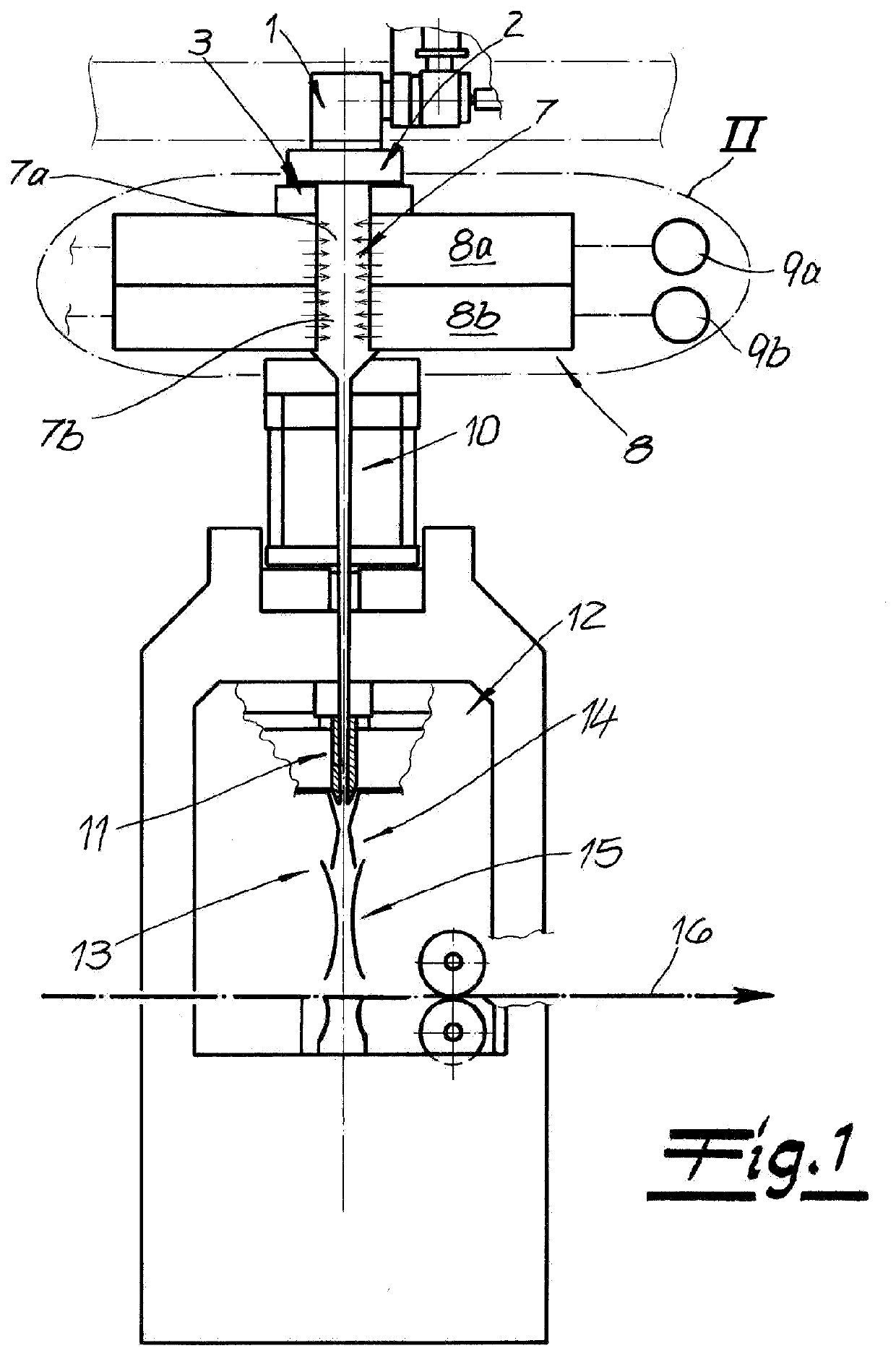
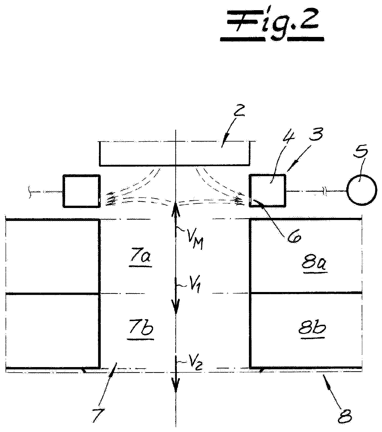
[0029]The figures show an apparatus for continuous production of a spunbond web of filaments of thermoplastic. The apparatus exhibits, first of all, a spinneret 1 with a nozzle plate 2 and nozzle holes therein for spinning the filaments that are not depicted. The spun filaments are then run past a monomer suction device 3 positioned below spinneret 1. This monomer suction device 3 is used to remove objectionable gasses from the system during the spinning process. The monomer suction device 3 exhibits a sucking chamber 4 as well as an exhaust ventilator 5 connected to the sucking chamber 4. A sucking slit 6 for sucking up the gasses is included in the lower region of the sucking chamber 4. Most practically, the sucking chamber 4 will be positioned both to the right and left of the filament formation space, as shown in the design example. The left half of the sucking chamber 4 is also connected to sucking ventilator 5.

[0030]A cooling chamber 7 into which process air for cooling the fi...


PUM

PropertyMeasurementUnit
angleaaaaaaaaaa
pressureaaaaaaaaaa
thicknessaaaaaaaaaa

Abstract

An apparatus for continuously making a spunbond web of filaments comprises a spinneret, a cooling chamber into which process air for can be introduced for the purpose of cooling the filaments, a monomer suction device between a spinneret and cooling chamber, a stretcher and a deposition device for depositing the filaments of the spunbond web. The cooling chamber is divided into two cooling compartments, and process air can be suctioned out from a first upper cooling compartment at a volumetric flow rate (VM) to a monomer suction device. Process air exits from the first upper cooling compartment at a volumetric flow rate (V1) into a second lower cooling compartment and from the first upper cooling compartment at a volumetric flow rate (V1) into a second lower cooling compartment. A ratio (VM / V1) is 0.1 to 0.35.

Description

CROSS REFERENCE TO RELATED APPLICATIONS[0001]This application is a division of U.S. patent application Ser. No. 14 / 758,968 filed 2 Jul. 2018 as the US-national stage of PCT application PCT / EP2013 / 074594 filed 25 Nov. 2013 and claiming the priority of European patent application 12195239.4 itself filed 3 Dec. 2013.FIELD OF THE INVENTION[0002]The invention relates to an apparatus for making a spunbond web from filaments with spinneret, cooling chamber, stretcher and a deposition device for deposition of the filaments for the spunbond web. The invention furthermore relates to a apparatus for making a spunbond web from filaments. The scope of the invention also includes the manufacture of a spunbond line via the so-called spunbond method by the apparatus of the invention. The filaments preferably consist of a thermoplastic resin, preferably of polypropylene, and more preferably of a specially modified polypropylene. Incidentally, filaments means continuous fibers or continuous filaments...

Claims


Application Information

Patent Timeline
Patent Type & Authority Applications(United States)
IPC IPC(8): D01D5/088D01F6/06D01D7/00D04H3/005D04H3/16D01D5/098
CPCD01F6/06B29C48/05D01D5/088B29D99/0078D04H3/16D01D5/0985D01D7/00D04H3/005B29L2031/731B29C48/345B29C48/87B29C48/92D04H3/02
Inventor CINQUEMANI, CLAUDIOFREY, DETLEFGEUS, HANS-GEORGSCHLAG, PETER
Owner REFENHAEUSER GMBH & CO KG MASCHFAB
Why Eureka
Try Eureka