Method of making a spunbond from filaments

Active Publication Date: 2019-10-01
REIFENHAUSER GMBH & CO
View PDF7 Cites 1 Cited by
  • Summary
  • Abstract
  • Description
  • Claims
  • Application Information

AI Technical Summary

Benefits of technology

The invention provides an apparatus and method for producing spunbond with uniformity and strength. It helps in avoiding issues such as diameter inhomogeneities and low titres filaments. The method is low-cost and low-effort, especially when polypropylene is used for spunbond manufacture.

Problems solved by technology

In many known Apparatuses or methods, the strength of the spunbond web is poor and especially the transverse strength of the spunbond web transversely to the direction of the machine or transversely to the transport direction.
Another problem is the diameter inhomogeneities in the deposited filaments.
These are small plastic assemblies that negatively affect the homogeneity of the spunbond web.
Furthermore, it is often difficult to produce filaments with high fineness or with low titres within the framework of the known measures.

Method used


Image

  • Method of making a spunbond from filaments
  • Method of making a spunbond from filaments

Examples


Embodiment Construction

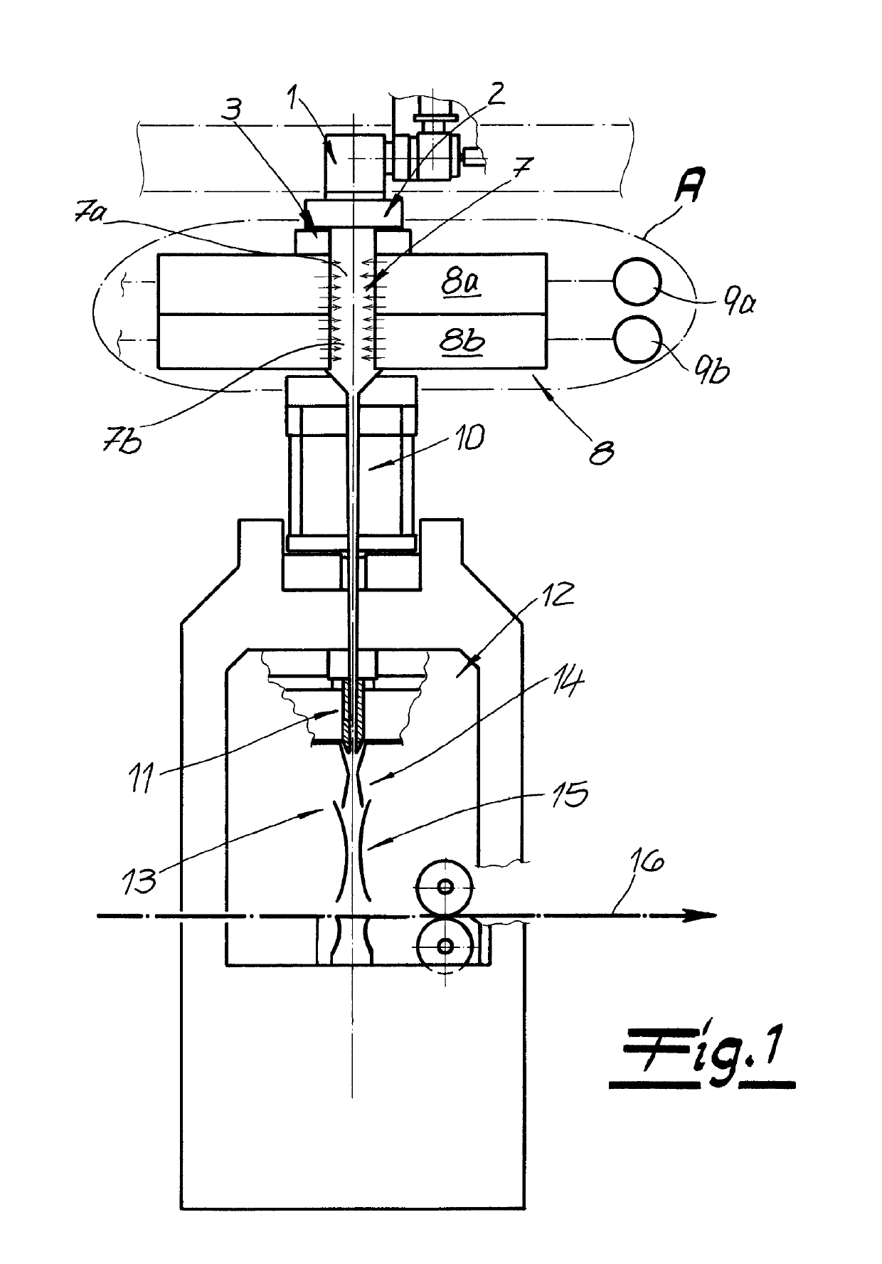
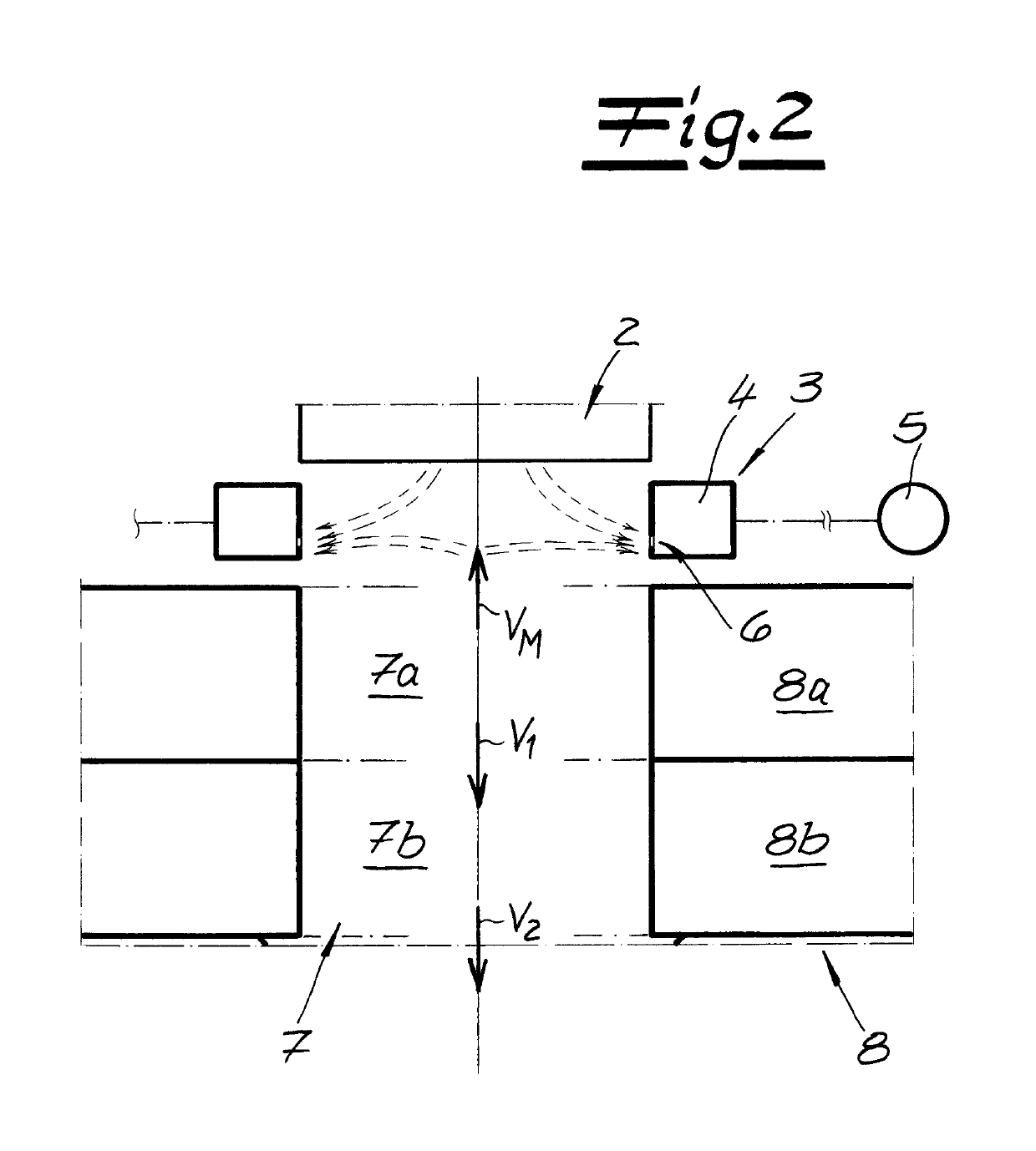
[0034]The figures show an apparatus for continuous production of a spunbond web of filaments of thermoplastic. The apparatus exhibits, first of all, a spinneret 1 with a nozzle plate 2 and nozzle holes therein for spinning the filaments that are not depicted. The spun filaments are then run past a monomer suction device 3 positioned below spinneret 1. This monomer suction device 3 is used to remove objectionable gasses from the system during the spinning process. The monomer suction device 3 exhibits a sucking chamber 4 as well as an exhaust ventilator 5 connected to the sucking chamber 4. A sucking slit 6 for sucking up the gasses is included in the lower region of the sucking chamber 4. Most practically, the sucking chamber 4 will be positioned both to the right and left of the filament formation space, as shown in the design example. The left half of the sucking chamber 4 is also connected to sucking ventilator 5.

[0035]A cooling chamber 7 into which process air for cooling the fi...


PUM

PropertyMeasurementUnit
Angleaaaaaaaaaa
Mass flow rateaaaaaaaaaa

Abstract

The invention relates to a device for producing a spun-bonded web from filaments, comprising spinnerets, a cooling chamber into which process air can be introduced in order to cool the filaments, a monomer suction device arranged between the spinnerets and the cooling chamber, a stretching unit, and a placing device for placing the filaments so as to form the spun-bonded web. The cooling chamber is divided into two cooling chamber portions. Process air can be suctioned out of a first upper cooling chamber portion to the monomer suction device with a volumetric flow rate Vm, and process air exits the first upper cooling chamber portion into a second lower cooling chamber portion with a volumetric flow rate V1. The volumetric flow rate ratio VM / V1 is 0.1 to 0.3.

Description

CROSS REFERENCE TO RELATED APPLICATIONS[0001]This application is the US-national stage of PCT application PCT / EP2013 / 074594 filed 25 Nov. 2013 and claiming the priority of European patent application 12195239.4 itself filed 3 Dec. 2013.FIELD OF THE INVENTION[0002]The invention relates to an apparatus for making a spunbond web from filaments with spinneret, cooling chamber, stretcher and a deposition device for deposition of the filaments for the spunbond web. The invention furthermore relates to a method of making a spunbond web from filaments. The scope of the invention also includes the manufacture of a spunbond line via the so-called spunbond method by means of the apparatus or the method of the invention. The filaments preferably consist of a thermoplastic resin, preferably of polypropylene, and more preferably of a specially modified polypropylene. Incidentally, filaments means continuous fibers or continuous filaments, which considerably differ from the much shorter staple fib...

Claims


Application Information

Patent Timeline
IPC IPC(8): D01D5/088D01F6/06D01D7/00D04H3/005D04H3/007D04H3/16D01D5/098B29D99/00B29C48/05B29L31/00
CPCD04H3/16D01D5/0985D04H3/005D01D7/00D01F6/06D04H3/007D01D5/088B29C48/05B29D99/0078B29L2031/731D01D5/098
Inventor CINQUEMANI, CLAUDIOFREY, DETLEFGEUS, HANS-GEORGSCHLAG, PETER
Owner REIFENHAUSER GMBH & CO
Why Eureka
Try Eureka