
Refiner plate segments with Anti-lipping feature

a technology of refiner plate and lip, which is applied in the field of mechanical refiners, can solve the problems of uneven wear pattern, shortening fibers, and overlapping bars between facing refiner plate segments, and achieves the effects of reducing the amount of lips, less pronounced, and prolonging the pulp quality produced

Active Publication Date: 2019-12-12
ANDRITZ INC
View PDF0 Cites 0 Cited by
  • Summary
  • Abstract
  • Description
  • Claims
  • Application Information

AI Technical Summary

Benefits of technology

This patent describes a mechanical refiner for improving the quality of fiber cutting in non-overlapping bars. The refiner comprises two facing refining assemblies, each with a backing structure and refiner plate segments. The refiner plate segments have alternating bars and grooves, creating a refining surface. The first refining assembly rotates around an axis of rotation, facing the refining surface of the second refining assembly. The refiner plate segments have terminal edges, which are not parallel to the outermost edge circumference of the second refining assembly. This design reduces the formation of lips at the terminal edges of the bars and makes the refiner plates easier to install and replace. It also improves the quality of pulp produced while reducing energy consumption during operation.

Problems solved by technology

Bars that overlap between facing refiner plate segments tend to wear away at a similar rate.
If the outer circumference of an operational refining assembly exceeds the outer circumference of the facing refining assembly, the radially outermost edges of the bars may not face any bars on the opposing refining assembly, thereby leading to an uneven wear pattern.
In this manner, the lips shorten the fibers and reduce the quality of the refined material.
For example, papers manufactured from short fibers tend to have weaker strength compared to papers manufactured from longer fibers.
However, even these best practices still leaves the lipping issues at many locations.
For example, taking appropriate amount of time to align the opposing refining assemblies properly can delay installation and result in prolonged production loss.
Furthermore, many modern refiners lack a retaining ring on the outer diameter (“O.D.”) of the stator, which some installers previously used to attempt to align the opposing refining assemblies.
However, even the use of complete discs requires precision alignment and the time pressure to install replacement refiner plates quickly often precludes precision alignment.
When the refiner disk size exceeds 26 inches, the installation of the whole disk becomes difficult and requires cranes and forklift trucks.
Full circle plates therefore crease in tight spaces during installation, create serious safety risks, and have the potential to extend losses of production during installation and maintenance periods should an accident or injury occur.

Method used


Image

  • Refiner plate segments with Anti-lipping feature
  • Refiner plate segments with Anti-lipping feature
  • Refiner plate segments with Anti-lipping feature

Examples


Embodiment Construction

[0035]The following detailed description of the preferred embodiments is presented only for illustrative and descriptive purposes and is not intended to be exhaustive or to limit the scope and spirit of the invention. The embodiments were selected and described to best explain the principles of the invention and its practical application. One of ordinary skill in the art will recognize that many variations can be made to the invention disclosed in this specification without departing from the scope and spirit of the invention.

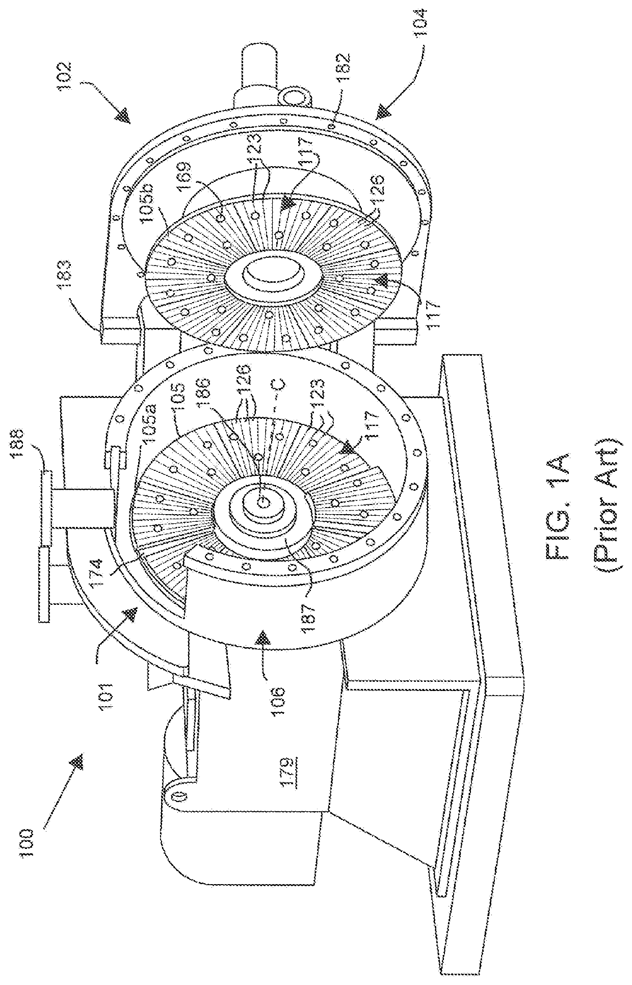
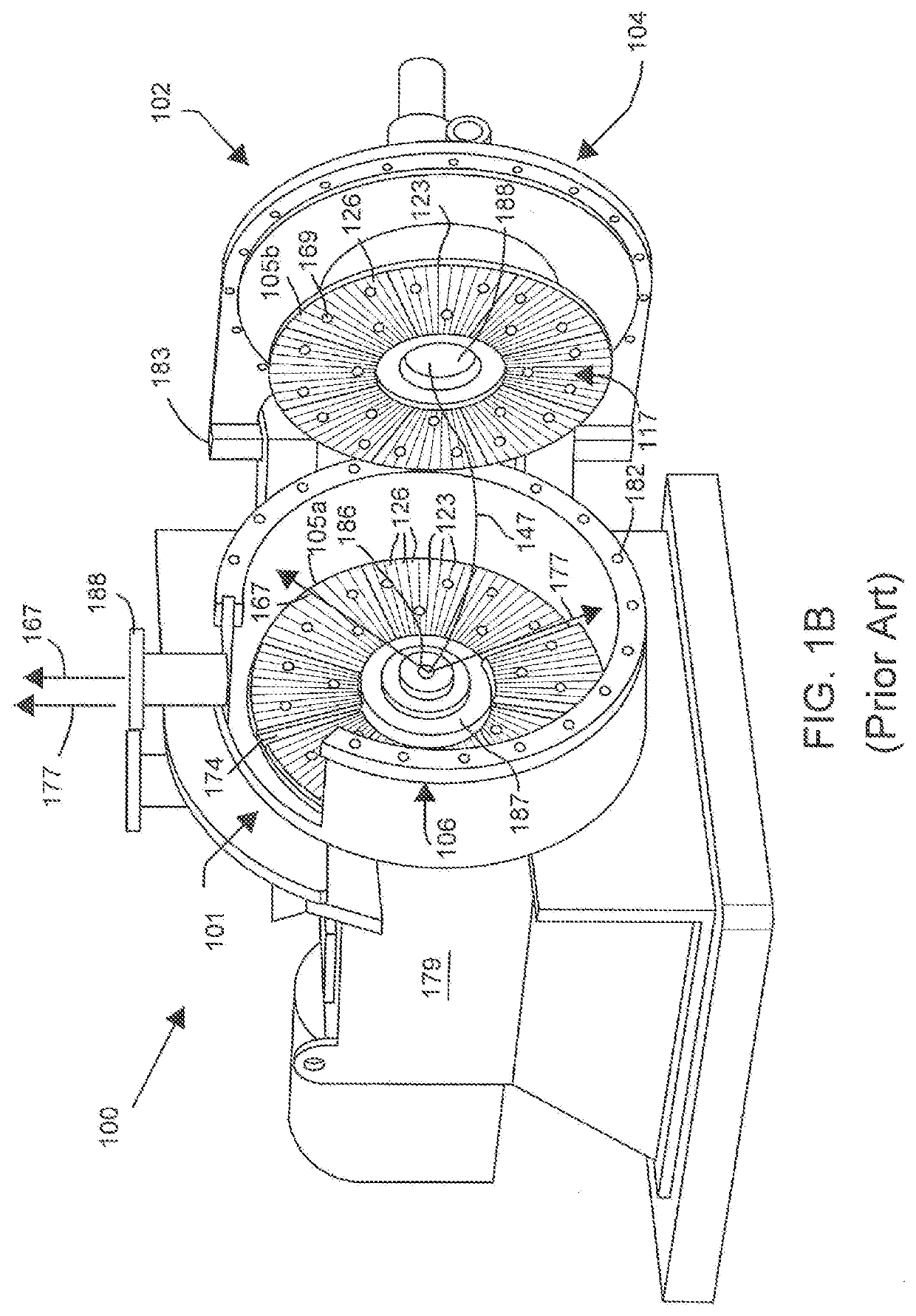
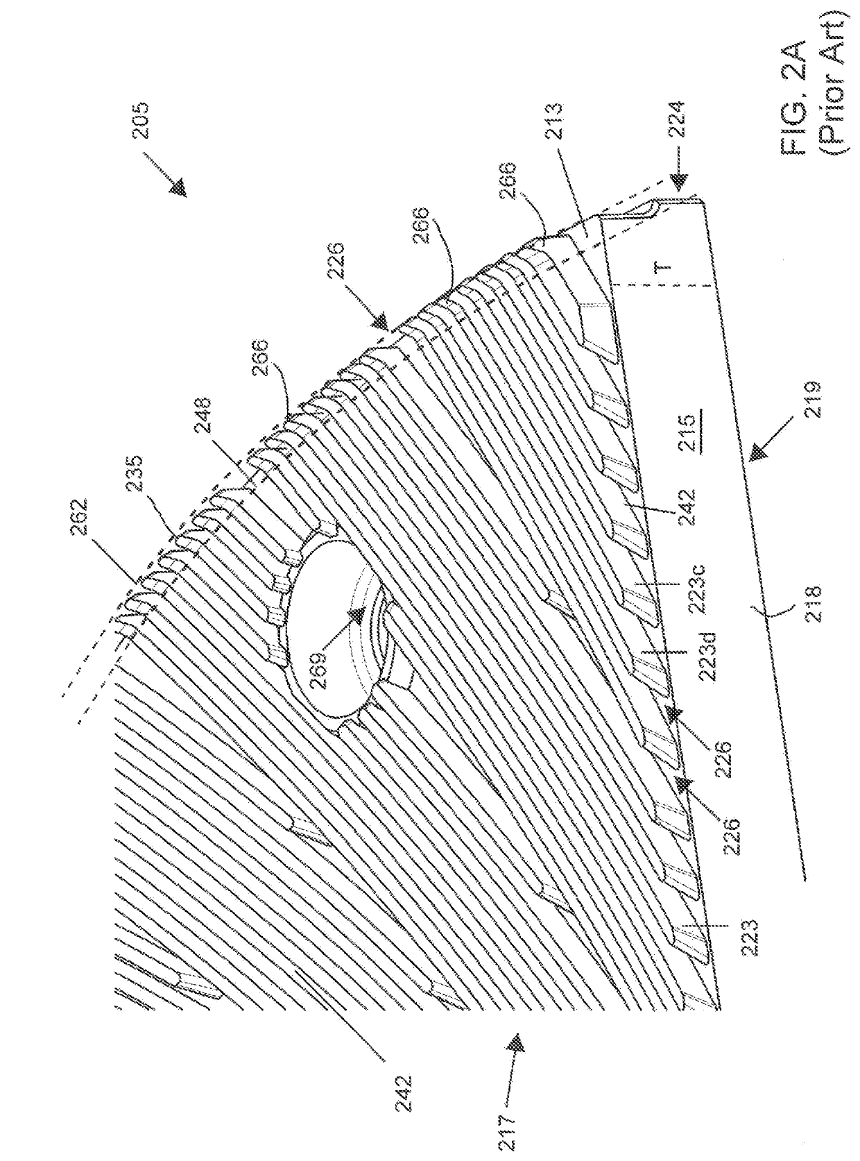
[0036]Similar reference characters indicate corresponding parts throughout the several views unless otherwise stated. For example, 218, 318, 518, to 918 all indicate the first lateral side of a depicted refiner plate segment. Although the drawings represent embodiments of various features and components according to the present disclosure, the drawings are not necessarily to scale and certain features may be exaggerated in order to better illustrate embodiments...


PUM

PropertyMeasurementUnit
edge angleaaaaaaaaaa
diameteraaaaaaaaaa

Abstract

A refiner comprising two or more facing refining assemblies, wherein each refining assembly comprises a backing structure and refiner plate segments engaged to the backing structure, wherein a series of alternating bars and grooves defines a refining surface on each refiner plate segment, wherein the refiner plate segments of the first refining assembly have a terminal edge perimeter defined by two or more terminal edges of bars disposed closest to the outer arc of the substrate of the first refining assembly, wherein the refiner plate segments of the second refining assembly have an outermost edge circumference defined by an outermost terminal edge of a bar disposed closest to the outer arc of the substrate of the second refining assembly facing the first refining assembly, and wherein the terminal edge perimeter of the first refining assembly is not parallel to the outermost edge circumference of the second refining assembly.

Description

RELATED APPLICATION[0001]This application claims the benefit under 35 U.S.C. § 119(e) of the earlier filing date of U.S. Provisional Patent Application No. 62 / 682,484 filed on Jun. 8, 2018, the entire contents of which are incorporated herein by reference.BACKGROUND OF THE INVENTIONTechnical Field[0002]The present disclosure relates generally to mechanical refiners configured to grind material into pulp, powders, or other particulate matter. The present disclosure relates more particularly to refiner plate segments for low-consistency refiners configured to separate, develop, and cut lignocellulosic material.[0003]Related Art[0004]In general, refiners can be characterized as either a high-consistency refiner (“HCR”) or a low-consistency refiner (“LCR”). HCRs generally grind feed material down into particulate matter that can be used in a number of products. When the feed material is lignocellulosic material, mechanical pulping refiners typically separate, develop, and cut lignocellu...

Claims


Application Information

Patent Timeline
Patent Type & Authority Applications(United States)
IPC IPC(8): D21D1/30
CPCD21D1/303D21D1/26D21D1/306B02C7/12
Inventor SINGHAL, ARVIND M.ANTENSTEINER, PETER
Owner ANDRITZ INC
Learn More