Antenna with Anti-Interference Arrangement and Its Manufacturing Method

a technology of interference arrangement and antenna, applied in the field of antenna, can solve the problems of poor contact between the center point of the radiation source and the reference ground, affecting the signal output stability of the antenna, time-consuming, etc., and achieve the effect of narrowing the bandwidth of the antenna, lowering the impedance of the antenna, and lowering the antenna's impedan

Active Publication Date: 2019-12-12
ZOU GAODI
View PDF0 Cites 8 Cited by
  • Summary
  • Abstract
  • Description
  • Claims
  • Application Information

AI Technical Summary

Benefits of technology

[0010]Another advantage of the invention is to provide an antenna with an anti-interference arrangement and method, wherein the anti-interference arrangement prevents electromagnetic wave signals received or generated by the antenna from being interfered by the nearby electromagnetic radiation frequency or the stray radiation frequency.
[0011]Another advantage of the invention is to provide an antenna with an anti-interference arrangement and method, wherein the impedance of the antenna is lowered to narrow the bandwidth thereof so as to prevent electromagnetic wave signals received or generated by the antenna from being interfered by the nearby electromagnetic radiation frequency or the stray radiation frequency.
[0012]Another advantage of the invention is to provide an antenna with an anti-interference arrangement and method, wherein the impedance of the antenna is lowered to enhance the radiating energy of the primary radiating wave within it

Problems solved by technology

Through the soldering process via the soldering material, the feed point of the radiation source may accidentally connect to the center point in a direct connecting manner.
At the same time, the center point of the radiation source may have a poor contact with the reference ground to affect the signal output stability of the antenna when the electromagnetic wave is outwardly radiated thereby.
Seriously, the antenna may be malfunctioned via the defect of soldering process.
In addition, through the conventional manufacturing process of the antenna, since the area of the center point is relatively small, it is time consuming to set the center point of the radiation source corresponding to the preset location of the reference ground.
Furthermore, once the radiation source is fixedly connected to one side of the reference source to form a defect of the antenna, the center point of the radiation source will not be electric

Method used

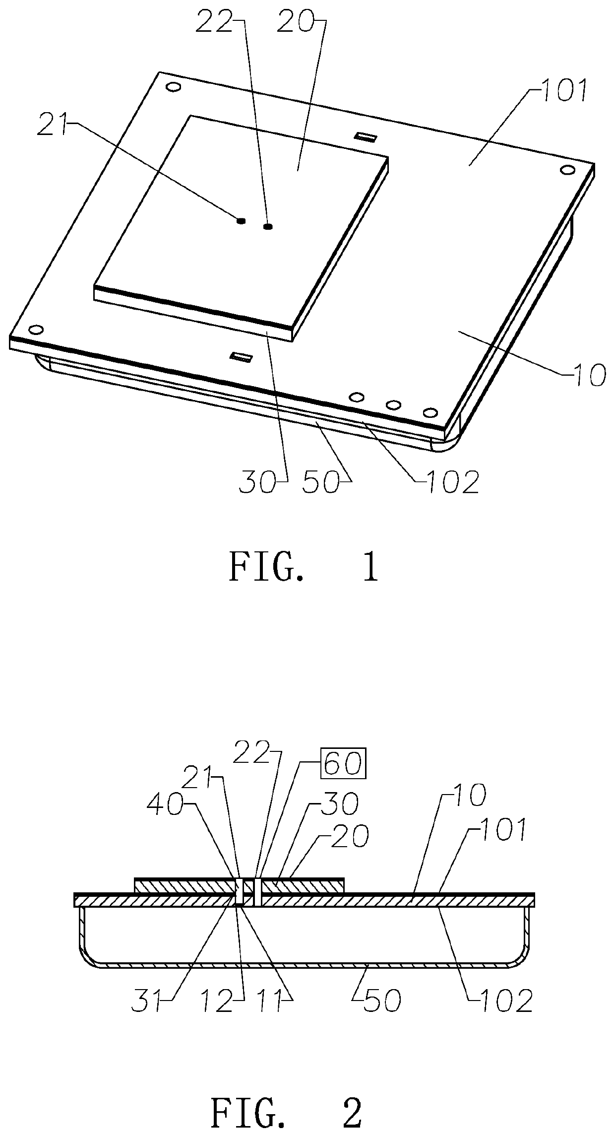
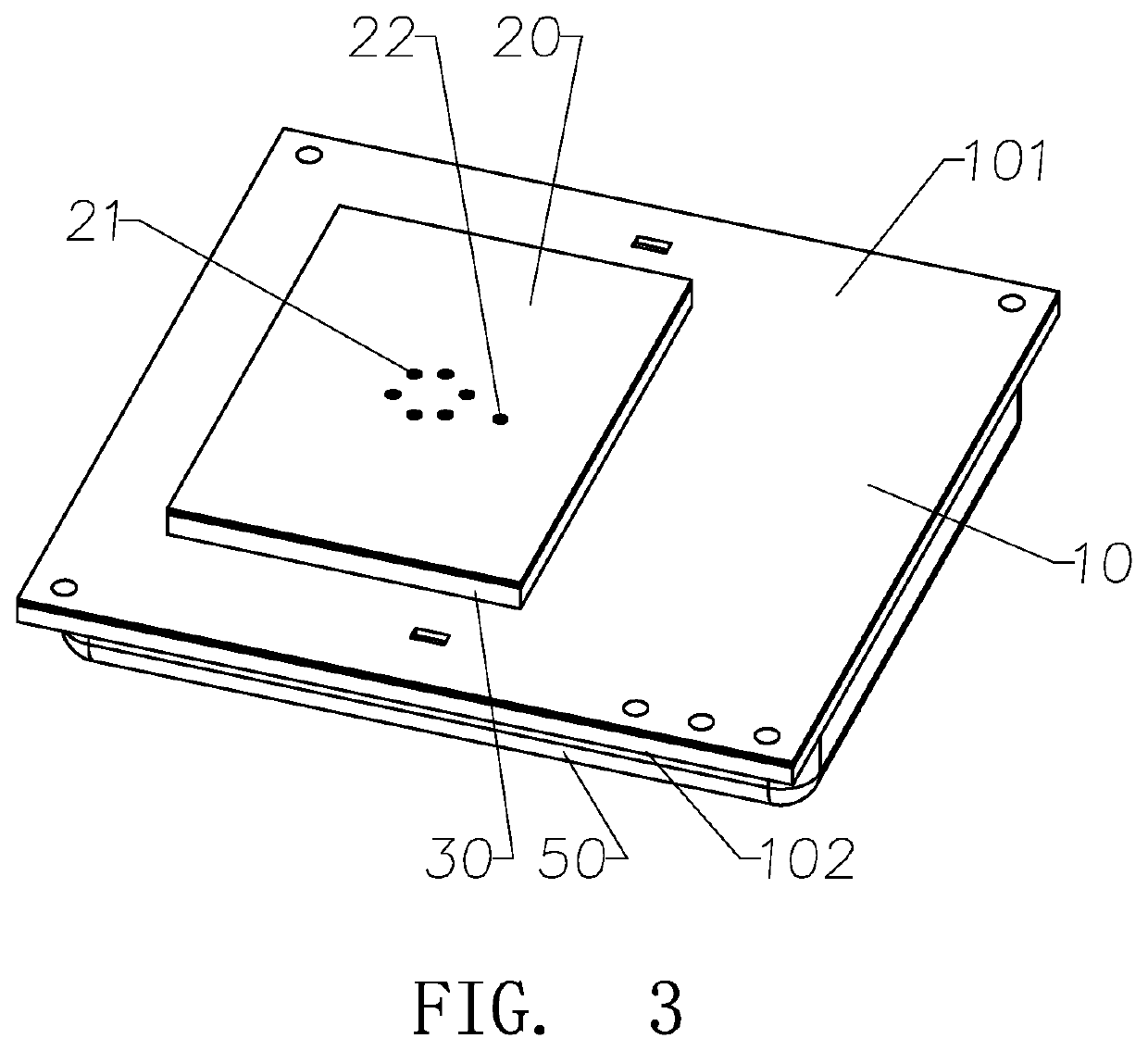
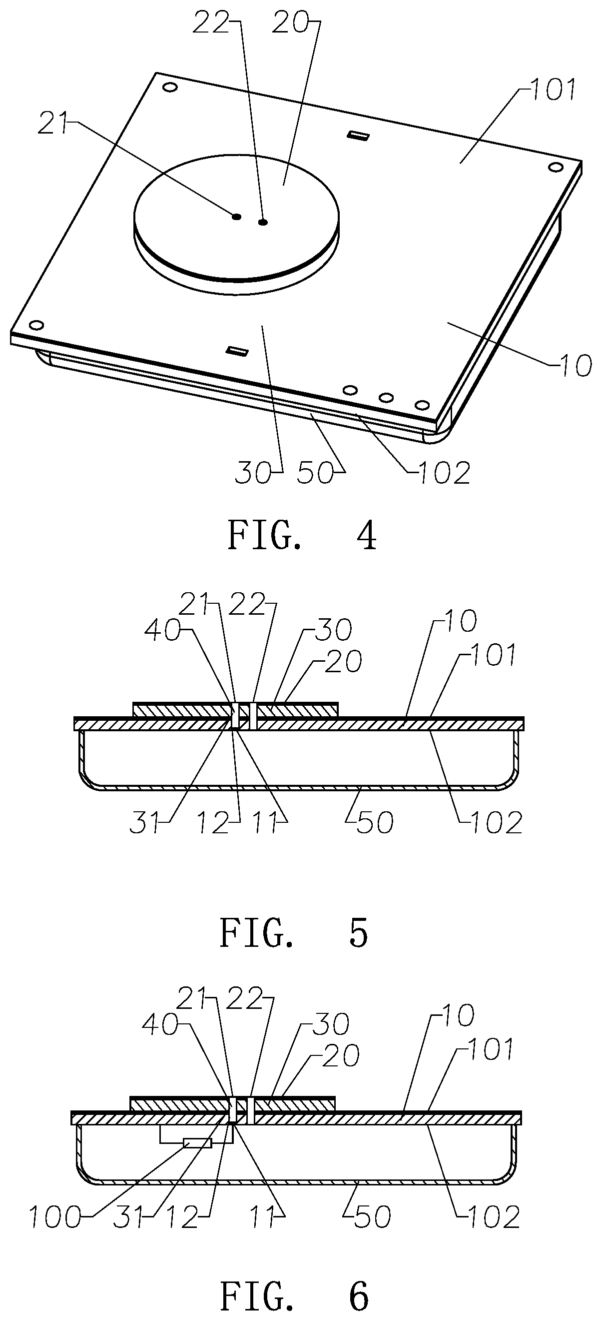

Image

  • Antenna with Anti-Interference Arrangement and Its Manufacturing Method
  • Antenna with Anti-Interference Arrangement and Its Manufacturing Method
  • Antenna with Anti-Interference Arrangement and Its Manufacturing Method

Examples


second embodiment

[0260]FIGS. 9 and 10 illustrate the present invention as an alternative mode thereof, wherein the antenna comprises a reference ground 10A, two radiating sources 20A, and an elongated connector 60A. The two radiating sources 20A are located adjacent to each other and are electrically connected by the elongated connector 60A. The elongated connector 60A is embodied as a micro-connection strip. A radiating clearance 30A is formed at each of the radiating sources 20A and the reference ground 10A.

[0261]Accordingly, the reference ground 10A has a first side 101A and an opposed second side 102A, wherein the radiating sources 20A are provided at the first side 101A of the reference ground 10A.

[0262]As shown in FIGS. 9 and 10, each of the radiating sources 20A has at least a radiating connection point 21A. The reference ground 10A has at least two reference ground connection points 11A. The radiating connection points 21A of the radiating sources 20A are electrically connected to the refere...

third embodiment

[0269]FIGS. 11 and 12 illustrate the present invention as another alternative mode thereof, wherein the antenna comprises a reference ground 10B, four radiating sources 20B, and three elongated connectors 60B. The reference ground 10B has a first side 101B and an opposed second side 102B. The four radiating sources 20B are formed in pair and are located adjacent to each other on the first side 101B of the reference ground 10B. The elongated connector 60A is embodied as a micro-connection strip. A radiating clearance 30B is formed at each of the radiating sources 20B and the reference ground 10A. The first elongated connectors 60B has two ends connecting to two adjacent radiating sources 20B in pair. The second elongated connector 60B has two ends connecting to two adjacent radiating sources 20B in another pair. The third elongated connector 60B has two ends connecting between the first and second elongated connectors 60B.

[0270]According to the preferred embodiment, the four radiatin...

fourth embodiment

[0281]FIGS. 13 and 14 illustrate the present invention as another alternative mode thereof, wherein the antenna comprises a reference ground 10C and at least a radiating source 20C. The radiating source 20C is disposed adjacent to the reference ground 10C to define a radiating clearance 30C between the radiating source 20C and the reference ground 10C. Accordingly, at least one radiating source 20C is electrically connected to the reference ground 10C.

[0282]In particular, the reference ground 10C has a first side 101C and an opposed second side 102C, wherein the radiating source 20C is disposed at the first side 101C of the radiating source 20C.

[0283]As shown in FIGS. 13 and 14, the radiating source 20C has one radiating connection point 21C and a feed point 22C, wherein the radiating connection point 21C is overlapped with the feed point 22C. The reference ground 10C has at least one reference ground connection point 11C. The antenna further comprises at least an electrical connect...


PUM


Abstract

An antenna includes a reference ground and at least a radiating source spacedly disposed at the reference ground to define a radiating clearance between the radiating source and the reference ground, wherein the radiating source is electrically connected to the reference ground to ground the radiating source so as to narrow a bandwidth of the antenna. When a electromagnetic excitation signal is received at a feed point of the radiating source, the bandwidth of the antenna is narrowed down to prevent any interference of the electromagnetic wave signal received or generated by the antenna in response to nearby electromagnetic radiation frequency or stray radiation frequency of the adjacent frequency bands.

Description

CROSS REFERENCE OF RELATED APPLICATION[0001]This is a Continuation-In-Part application that claims the benefit of priority under 35 U.S.C. § 120 to a non-provisional application, application number Ser. No. 16 / 035,689, filed Jul. 15, 2018, which is a non-provisional application that claims which claims priority under 35 U.S.C. 119(a-d) to Chinese application number 201810595979.X, filed Jun. 11, 2018. The afore-mentioned patent application is hereby incorporated by reference in its entirety.[0002]This application, also claimed priority to Chinese application number CN2018113687195, filed Nov. 16, 2018 and Chinese application number CN2018114730099, filed Dec. 4, 2018.NOTICE OF COPYRIGHT[0003]A portion of the disclosure of this patent document contains material which is subject to copyright protection. The copyright owner has no objection to any reproduction by anyone of the patent disclosure, as it appears in the United States Patent and Trademark Office patent files or records, but...

Claims


Application Information

Patent Timeline
IPC IPC(8): H01Q9/06H01Q1/38
CPCH01Q9/065H01Q1/38H01Q1/48H01Q1/52
Inventor ZOU, GAODIZOU, XIN
Owner ZOU GAODI
Why Eureka
Try Eureka