Magnetic field sensor using acoustically driven ferromagnetic resonance

a magnetic field sensor and acoustically driven technology, applied in the direction of magnetostrictive property measurement, analysis using electron paramagnetic resonanace, mechanical vibration separation, etc., can solve problems such as incompatibility with device applications

a magnetic field sensor and acoustically driven technology, applied in the direction of magnetostrictive property measurement, analysis using electron paramagnetic resonanace, mechanical vibration separation, etc., can solve problems such as incompatibility with device applications

US20190385586A1Pending Publication Date: 2019-12-19RGT UNIV OF CALIFORNIA

Image

  • Magnetic field sensor using acoustically driven ferromagnetic resonance
  • Magnetic field sensor using acoustically driven ferromagnetic resonance
  • Magnetic field sensor using acoustically driven ferromagnetic resonance

Examples


Embodiment Construction

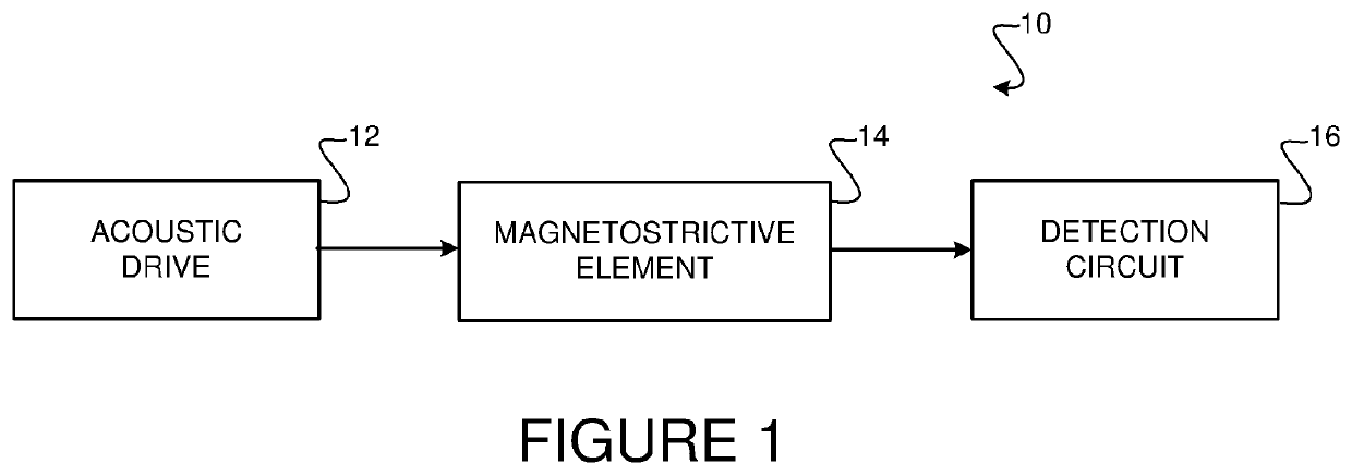
[0013]FIG. 1 shows a block diagram of an embodiment of an acoustically driven ferromagnetic device (ADFMR) 10. These devices may be used as field sensors by measuring transmitted power, among many other applications. The acoustic drive portion 12 of the device may consist of one of many different types of acoustic resonators, including surface acoustic wave (SAW) resonators, film bulk acoustic resonators (FBAR), and high-tone bulk acoustic resonators (HBAR).

[0014]The acoustic drive portion generates an acoustic wave at or near the ferromagnetic resonance of a magnetostrictive element, discussed in more detail below. As used here the phrase โ€˜at the ferromagnetic resonanceโ€™ includes a reasonable variation from the exact ferromagnetic resonance of the magnetostrictive element. The region of ferromagnetic resonance considered to be โ€˜at the ferromagnetic resonanceโ€™ is the region in which the FMR-related absorption is greater than 10%, approximately 0.4 dB. In addition, for purposes of th...


PUM


Abstract

An acoustically driven ferromagnetic resonance (ADFMR) device includes a piezoelectric element, a pair of transducers arranged to activate the piezoelectric element to generate an acoustic wave, a magnetostrictive element arranged to receive the acoustic wave, and a readout circuit to detect one of either a change in the magnetostrictive element or a change in the acoustic wave.

Description

CROSS REFERENCE TO RELATED APPLICATION[0001]This application claims priority to and the benefit of U.S. Provisional Application No. 62 / 434,122 filed Dec. 14, 2016, which is incorporated herein by reference in its entiretyGOVERNMENT SUPPORT[0002]This invention was made with government support under Grant Number 1160504 awarded by the National Science Foundation. The government has certain rights in the invention.BACKGROUND[0003]Ferromagnetic resonance (FMR) measures magnetic properties of materials by detecting the precessional motion in of the magnetization in a ferromagnetic sample. Different types of FMR include externally-driven FMR and current-driven FMR. FMR can be excited using a variety of techniques, like cavity excitation, stripline excitation, spin transfer torque, and spin orbit torque, among others These applications are typically not compatible with device applications. They require large cavities, high power drive and use large sample volume in order to be effective.[0...

Claims


Application Information

Patent Timeline
19 Dec 2019
Publication
US20190385586A1
IPC
G10K11/36; G01R33/18
CPC
G10K11/36; G01R33/18; G01R33/1284; B06B1/06; G01R33/075; G01R33/0325; G01R33/0327; G01R33/096
Inventors
SALAHUDDIN, SAYEEF; LABANOWSKI, DOMINIC E.