Drive device for correcting angular deviation between shafts

Active Publication Date: 2019-12-19
RICOH KK
View PDF2 Cites 3 Cited by
  • Summary
  • Abstract
  • Description
  • Claims
  • Application Information

AI Technical Summary

Benefits of technology

[0006]At least one aspect of this disclosure provides a drive device including a first motor, a second motor, and circuitry. The first motor includes a first rotation detector and is configured to rotate a driven shaft to apply a driving torque to the driven shaft. The second motor includes a second rotation detector and is configured to rotate the driven shaft to reduce backlash between the first motor and the driven shaft. The circuitry is configured to control the first motor and the second motor, based on a detection signal of the second

Problems solved by technology

However, due to the rigidity of a reduction gear from the multiple motors to the output shaft, an angular deviation corresponding to the load torque oc

Method used


Image

  • Drive device for correcting angular deviation between shafts
  • Drive device for correcting angular deviation between shafts
  • Drive device for correcting angular deviation between shafts

Examples


Example

Embodiment 1

[0036]A description is given of a drive device according to Embodiment 1.

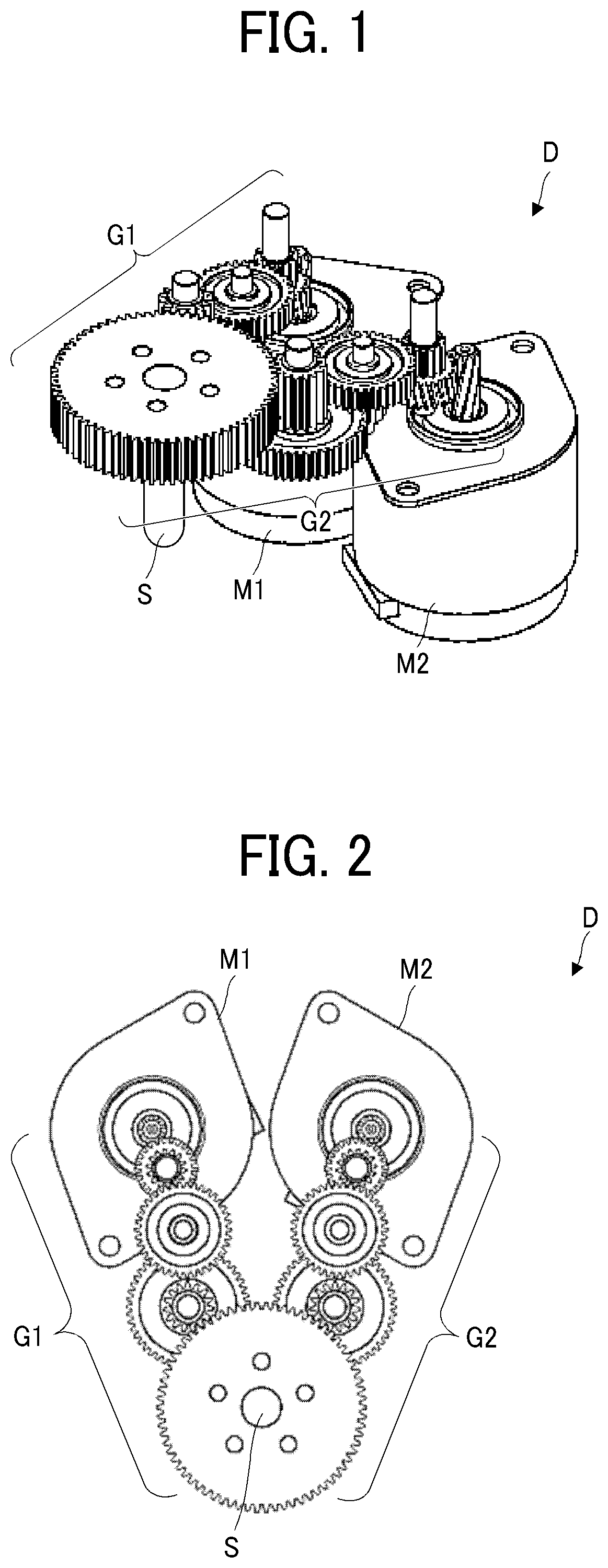
[0037]FIG. 1 is a perspective view illustrating an example of a drive unit D that is driven using double motor control. FIG. 2 is a plan view illustrating the drive unit D.

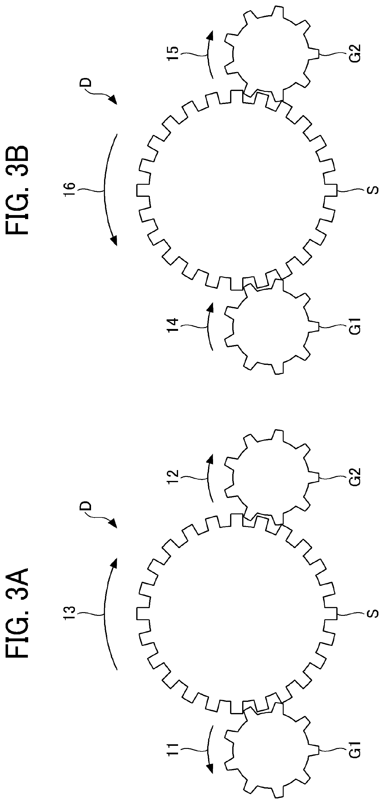
[0038]As illustrated in FIGS. 1 and 2, the drive unit D includes a motor M1, a motor M2, an output shaft S, a transmission unit G1, and a transmission unit G2. It is to be noted that the drive unit D further includes a motor shaft encoder E1 that measures an angle θ1 of the motor M1 and a motor shaft encoder E2 that measures an angle θ2 of the motor M2. The motor shaft encoder E1 may be externally attached to the motor M1 or may be incorporated in the motor M1. Similarly, the motor shaft encoder E2 may be externally attached to the motor M2 or may be incorporated in the motor M2.

[0039]The motor M1 functions as a first motor and the motor M2 functions as a second motor. The motor shaft encoder E1 functions as a first rotation detec...

Example

Embodiment 2

[0171]Next, a description is given of an example of another drive device 100a according to Embodiment 2 with reference to a drawing.

[0172]It is to be noted that, in a case in which the units and components of the drive device 100a according to Embodiment 2 are the same as the units and components of the drive device 100 according to Embodiment 1, the description of the units and components of the drive device 100a of Embodiment 2 may be omitted.

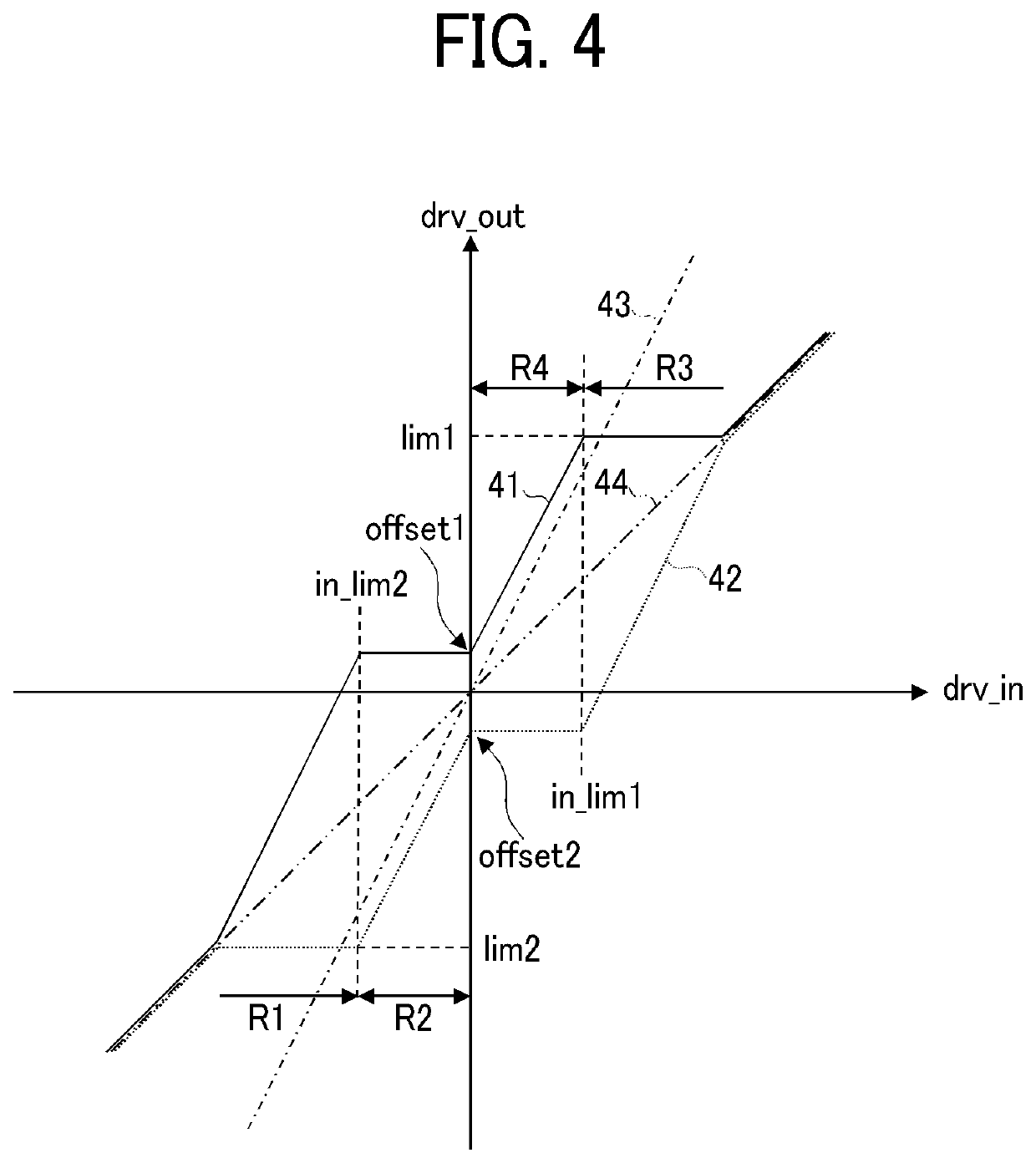
[0173]In the drive device 100 according to Embodiment 1, the correcting unit 135 corrects the detection value ϕ1 or the detection value ϕ2 by using a set of the correction values θoffset1, θoffset2, θlim1, and θlim2. However, in actual control of the output shaft S, the influence of gravity differs depending on the output conditions such as the rotation direction, angle, and speed of the output shaft S, and the load torque may change. In a case in which the load torque changes, the appropriate correction value changes.

[0174]For th...


PUM


Abstract

A drive device includes a first motor, a second motor, and circuitry. The first motor includes a first rotation detector and is configured to rotate a driven shaft to apply a driving torque to the driven shaft. The second motor includes a second rotation detector and is configured to rotate the driven shaft to reduce backlash between the first motor and the driven shaft. The circuitry is configured to control the first motor and the second motor, based on a detection signal of the second rotation detector.

Description

CROSS-REFERENCE TO RELATED APPLICATION[0001]This patent application is based on and claims priority pursuant to 35 U.S.C. § 119(a) to Japanese Patent Application No. 2018-113111, filed on Jun. 13, 2018, in the Japan Patent Office, the entire disclosure of which is hereby incorporated by reference herein.BACKGROUNDTechnical Field[0002]This disclosure relates to a drive device for correcting an angular deviation between shafts.Related Art[0003]A technology of multi-motor control is known to control rotation of a common output shaft that is driven by multiple motors to enhance an increase in torque and a reduction in backlash. In particular, a double-motor control technology is used to control two motors. Further, there is another technology in which the angle of an output shaft is controlled with feedback control of the detection signal obtained by a motor shaft encoder or an output shaft encoder, so that the position and speed of the output shaft are controlled.[0004]In the double-mo...

Claims


Application Information

Patent Timeline
IPC IPC(8): H02P5/56H02P5/753
CPCH02P5/56H02P5/753H02P5/747
Inventor KOIKE, TAKAHISA
Owner RICOH KK
Why Eureka
Try Eureka