Forced induction system

a technology of forced induction system and forced induction, which is applied in the direction of engine controllers, combustion engines, machines/engines, etc., can solve the problems of torque shock and increase in cost, and achieve the effects of reducing the occurrence of torque shock due to fluctuation in boost pressure, and reducing the impact of boost pressur

Inactive Publication Date: 2019-12-26
TOYOTA IND CORP
View PDF0 Cites 1 Cited by
  • Summary
  • Abstract
  • Description
  • Claims
  • Application Information

AI Technical Summary

Benefits of technology

[0006]An object of the present disclosure is to provide a forced induction system that can reduce the fluctuation in boost pressure at the time of switching between forced induction modes involving a plurality of forced induction devices, in a simpler configuration.
[0008]As such, by controlling the first opening degree to be equal to the second opening degree during the approach-run operation, the respective turbine wheels of the first forced induction device and the second forced induction device can be supplied with equal levels of exhaust energy. This provides a good balance between the decrease in the first boost pressure and the increase in the second boost pressure, and allows a high boost pressure at which the second boost pressure reaches the first boost pressure. Thus, when the first forced induction mode switches to the second forced induction mode, the decline in the first boost pressure can be curbed. As a result, the occurrence of torque shock due to fluctuation in boost pressure can be reduced. This control can be performed by equalizing the opening degrees of the variable nozzle mechanisms, which means that the fluctuation in boost pressure can be reduced in a simple configuration.

Problems solved by technology

Execution of such switching control may cause a torque shock if the boost pressure fluctuates before and after the switching.
This may lead to increase in cost.

Method used


Image

  • Forced induction system
  • Forced induction system
  • Forced induction system

Examples


Embodiment Construction

[0019]An embodiment of the present disclosure is hereinafter described with reference to the drawings. In the following description, identical components are identically denoted. They also have identical names and functions. Therefore, the detailed description of such components is not repeated.

[0020]

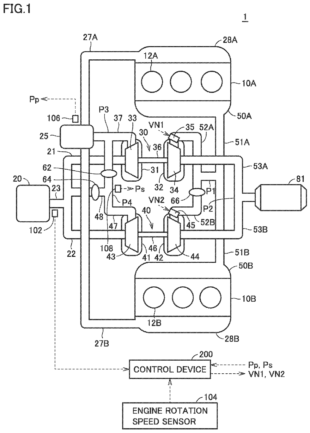
[0021]FIG. 1 is a diagram showing one example of a general configuration of an engine 1 in the present embodiment. With reference to FIG. 1, this engine 1 is mounted on a vehicle as a driving source for traveling, for example. Although the present embodiment describes a case in which the engine 1 is a diesel engine as an example, the engine 1 may be a gasoline engine, for example.

[0022]The engine 1 includes banks 10A, 10B, an air cleaner 20, an intercooler 25, intake manifolds 28A, 28B, forced induction devices 30, 40, exhaust manifolds 50A, 50B, an exhaust treatment device 81, and a control device 200.

[0023]The bank 10A has a plurality of cylinders 12A. The bank 10B has a plurality of ...


PUM


Abstract

When the forced induction mode is a single forced induction mode, and when it is determined that there is a request for switching to a twin forced induction mode, the control device executes a process including the step of executing an approach-run operation, the step of executing a control for equalizing the VN opening degree, and the step of switching to the twin forced induction mode when it is determined that a second boost pressure has reached a first boost pressure.

Description

[0001]This nonprovisional application is based on Japanese Patent Application No. 2018-119696 filed on Jun. 25, 2018 with the Japan Patent Office, the entire contents of which are hereby incorporated by reference.BACKGROUND[0002]The present disclosure relates to control of a forced induction system including a plurality of forced induction devices connected in parallel.DESCRIPTION OF THE BACKGROUND ART[0003]As a forced induction system to perform a forced induction of the intake air of an engine, a system including a plurality of forced induction devices connected in parallel has been known, for example. For example, a forced induction system including two forced induction devices connected in parallel performs switching control for switching between a forced induction mode in which one of the two forced induction devices is used to perform the forced induction of the intake air of the engine (hereinafter also referred to as a single forced induction mode), and a forced induction mo...

Claims


Application Information

Patent Timeline
Patent Type & Authority Applications(United States)
IPC IPC(8): F02B37/00F02D23/00F02B33/40F02B37/24
CPCF02D23/00F02B37/001F02B37/24F02B33/40F02B37/002F02B37/007F02B37/013F02B2037/122F02B2037/125Y02T10/12
Inventor KAMIYA, YOSHIAKINARUSE, YUYA
Owner TOYOTA IND CORP
Why Eureka
Try Eureka