Supercharge Your Innovation With Domain-Expert AI Agents!

Pole clamp assembly for medical devices

a technology for medical devices and clamps, applied in the field of clamps, can solve the problems of time-consuming and unfavorable utilization, and achieve the effects of convenient use and speed, adequate space, and efficient space managemen

Active Publication Date: 2020-01-02
SMITHS MEDICAL ASD INC
View PDF0 Cites 0 Cited by
  • Summary
  • Abstract
  • Description
  • Claims
  • Application Information

AI Technical Summary

Benefits of technology

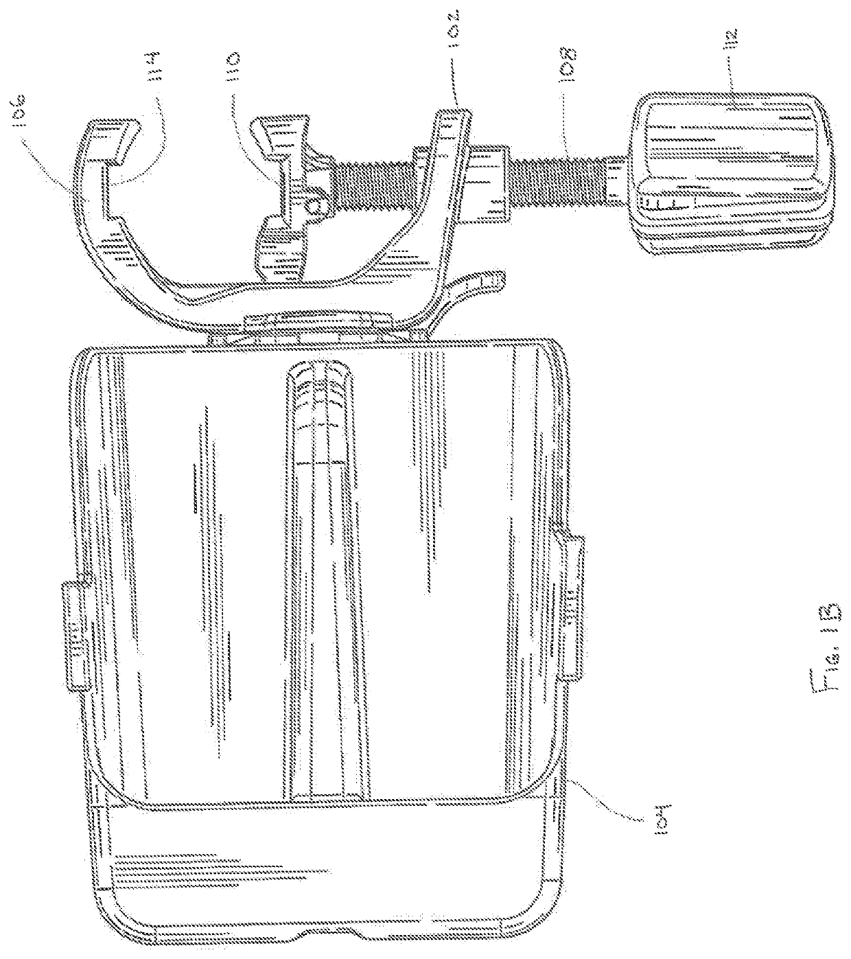
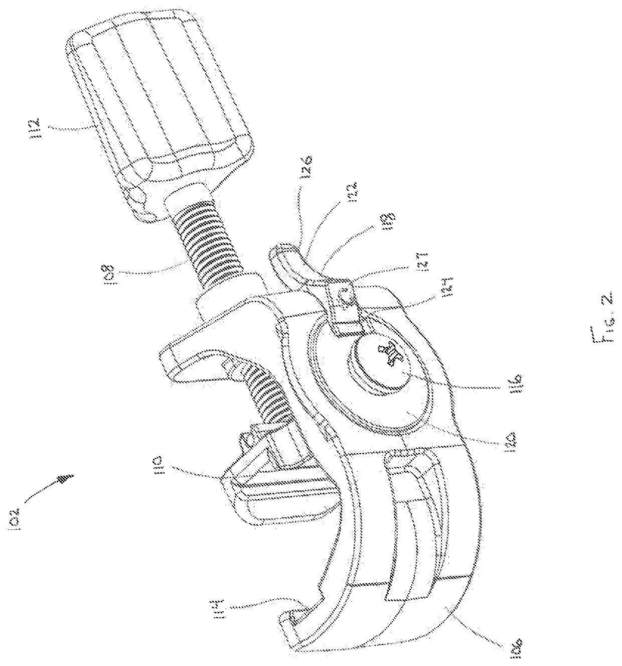
The present invention provides pole clamp assemblies that make it easy for medical devices to be quickly and securely mounted, removed, and repositioned in relation to a support structure. These assemblies also efficiently manage space along the support structure to ensure that multiple medical devices can be mounted without interfering with each other.

Problems solved by technology

While such pole clamp assemblies have been used for many years, they can be awkward and time-consuming to utilize.

Method used


Image

  • Pole clamp assembly for medical devices
  • Pole clamp assembly for medical devices
  • Pole clamp assembly for medical devices

Examples


second embodiment

[0038]Referring to FIG. 4, a docking member, 204, is depicted in accordance with the disclosure. In this embodiment, a longitudinal axis of the projection 258 can extend at an oblique angle relative to the hub face 234, such that a medical device selectively coupled to the docking number 204 would thereby be tilted slightly upward from a horizontal plane when attached to a substantially vertical IV pole or other supporting structure. In an embodiment, this can be accomplished by orienting the hub face 234 at an angle α with respect to an exterior surface 266 of the hub portion 230. As depicted in the example of FIG. 4, the angle α can be approximately 3°. In other embodiments, the angle α can be between 0-10°. Other angular configurations are also contemplated.

[0039]The docking member 204 can further include one or more channels or indents 268, which can be positioned on the respective sides of the docking member body 228. In some embodiments, the one or more indents 268 can further...

third embodiment

[0040]Referring to FIGS. 5A-B, a docking member 304 is depicted in accordance with the disclosure. In this embodiment, the projection 358 is primarily present in or limited to side portions 356A / B, and optionally a portion of the bottom surface 332, but lacking a top surface (as is present in previous embodiments). The distal end (away from the hub portion) of projection 358 is thus configured to be open, as depicted in FIGS. 5A and 5B. In some embodiments, omission of a top surface on projection 358 aids in the insertion and withdrawal of the projection 358 into and out of a corresponding retaining feature of a medical device. In particular, where the retaining feature of a medical device includes a handle for gripping the medical device, a projection 358 that is primarily limited to side portions 356A / B and a bottom surface 332 enables gripping of the handle of the medical device with limited or no interference from the projection 358.

[0041]In place of a keel member and top surfac...


PUM


Abstract

A pole clamp assembly is configured to facilitate removable coupling of one or more medical devices to a support structure. The pole clamp assembly includes a pole clamp that is configured to selectively grip the supporting structure. The pole clamp includes a fastener hub and a locking mechanism. A docking member is configured to operably couple a medical device of the one or more medical devices to the pole clamp. The docking member includes structure defining a fastener hub aperture and one or more recesses into which a portion of the locking mechanism can selectively reside. The locking mechanism is shiftable between a non-engaged position in which the docking member is rotatable relative to the pole clamp, and an engaged position in which rotation of the docking member relative to the pole clamp is inhibited.

Description

RELATED APPLICATION INFORMATION[0001]This application claims the benefit of U.S. Provisional Application No. 62 / 487,189, filed Apr. 19, 2017, the contents of which are fully incorporated herein by reference.TECHNICAL FIELD[0002]The present disclosure relates generally to a clamp for securing a medical instrument to a pole, and more particularly to such a pole clamp configured to easily engage and disengage a medical device or group of medical devices to a pole.BACKGROUND[0003]In the hospital or clinical environment, it is often necessary to provide medical devices or instrumentation in proximity to patients, such as near a patient's bedside. For example, during many medical treatments and procedures, patients are provided with intravenous fluid delivery for the infusion of fluids to prevent dehydration, preserve electrolyte balance or deliver other medicaments, such as antibiotics, blood clotting agents, analgesics, and other fluid and / or fluid-like substances. Frequently, intraveno...

Claims


Application Information

Patent Timeline
Patent Type & Authority Applications(United States)
IPC IPC(8): A61B90/57A61M5/14
CPCA61M5/1415A61M2209/082A61B2090/571A61B90/57F16B2/12
Inventor LACY, CHRISTOPHER ALLENKRAUTBAUER, KEVINPLAGER, STEVEN
Owner SMITHS MEDICAL ASD INC
Features
  • R&D
  • Intellectual Property
  • Life Sciences
  • Materials
  • Tech Scout
  • Unparalleled Data Quality
  • Higher Quality Content
  • 60% Fewer Hallucinations
Learn More