Pneumatic tire

Inactive Publication Date: 2020-01-02
TOYO TIRE & RUBBER CO LTD
View PDF0 Cites 0 Cited by
  • Summary
  • Abstract
  • Description
  • Claims
  • Application Information

AI Technical Summary

Benefits of technology

[0021]According to this configuration, it is possible to secure the rubber thickness of the groove bottom from the belt by the projections arranged on both sides of the protrusion while ensuring the sludge discharge performance by the protrusion extending in the tire width direction. Further, the plurality of projections are provided, so that the drainage property when the tire is worn is maintained.
[0022]According to the pre

Problems solved by technology

However, in the conventional pneumatic tire, the projections formed in the groove are only stone ejectors for preventing pebbles and the like from getting stuck in the groove.
The distance (thickness) from the groove bottom to a belt as an internal component cannot be suf

Method used


Image

  • Pneumatic tire
  • Pneumatic tire
  • Pneumatic tire

Examples


Embodiment Construction

[0033]Hereinafter, embodiments of the present invention are described with reference to the attached drawings. It should be noted that the following description is merely exemplary in nature and is not intended to limit the present invention, an object for application, or a usage. In addition, the drawings are schematic, and ratios of dimensions and the like are different from actual ones.

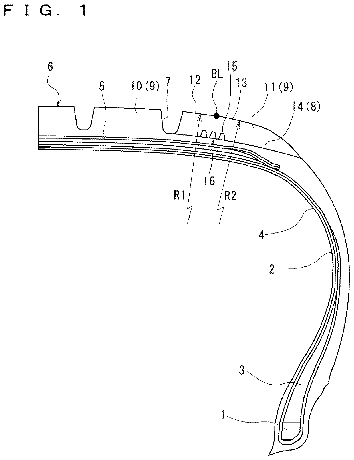
[0034]FIG. 1 is a meridian half sectional view of a pneumatic tire according to the present embodiment. The pneumatic tire has a carcass ply 2 stretched between a pair of bead cores 1. Both ends of the carcass ply 2 are wound up on the bead cores 1 and bead fillers 3 provided in connection with the bead cores 1. An inner liner 4 is provided inside the carcass ply 2. A plurality of belts 5 are wound around the outer peripheral side of the carcass ply 2. An outer peripheral side of the belts 5 is a tread portion 6.

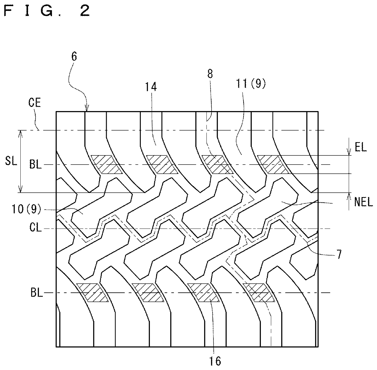
[0035]FIG. 2 is a development view for illustrating a part of the tread portion 6 of th...


PUM


Abstract

A pneumatic tire includes, in a tread portion, a plurality of blocks formed by a plurality of main grooves extending in a tire circumferential direction and a plurality of lateral grooves extending in a tire width direction so as to intersect the main grooves. The lateral grooves each include a reinforcement region in which a plurality of projecting portions are formed at a groove bottom. In the reinforcement region, at least one projecting portion is arranged on any line extending in the tire circumferential direction.

Description

CROSS-REFERENCE TO RELATED APPLICATIONS[0001]This application claims priority of Japanese Patent Application No. 2018-125199 filed on Jun. 29, 2018, the content of which is incorporated herein by reference.BACKGROUND OF THE INVENTIONTechnical Field[0002]The present invention relates to a pneumatic tire.Related Art[0003]Conventionally, there has been known a pneumatic tire in which a plurality of button-shaped stone ejectors are provided in each groove formed in a tread (see, for example, JP 3822337 B2).[0004]However, in the conventional pneumatic tire, the projections formed in the groove are only stone ejectors for preventing pebbles and the like from getting stuck in the groove. In the region where the stone ejectors are formed, there are lines where the stone ejectors are not located when viewed in the tire circumferential direction. The distance (thickness) from the groove bottom to a belt as an internal component cannot be sufficiently secured on these lines, and cracks are lia...

Claims


Application Information

Patent Timeline
IPC IPC(8): B60C11/13
CPCB60C2011/1361B60C11/1353B60C11/11B60C11/13B60C11/1369B60C2011/0358B60C11/01
Inventor OHARA, MASAAKI
Owner TOYO TIRE & RUBBER CO LTD
Why Eureka
Try Eureka