Lidar sensing device

a sensing device and lidar technology, applied in the direction of measurement devices, using reradiation, instruments, etc., can solve the problems of increasing the number of components, reduce the number of parts, reduce the blockage area, and improve the efficiency of light receiving

Pending Publication Date: 2020-01-02
HYUNDAI MOBIS CO LTD
View PDF7 Cites 0 Cited by
  • Summary
  • Abstract
  • Description
  • Claims
  • Application Information

AI Technical Summary

Benefits of technology

[0011]Exemplary embodiments of the present invention are directed to a LiDAR sensing device, which reduces a blockage area, thus improving light receiving efficiency and decreasing the number of parts.

Problems solved by technology

The conventional LiDAR sensor is problematic in that the reflecting mirror is installed to turn an optical path and thereby reduce the size of the LiDAR sensor, so that the number of components is increased.

Method used


Image

  • Lidar sensing device
  • Lidar sensing device
  • Lidar sensing device

Examples


first embodiment

[0039]First, a LiDAR sensing device in accordance with the present invention will be described.

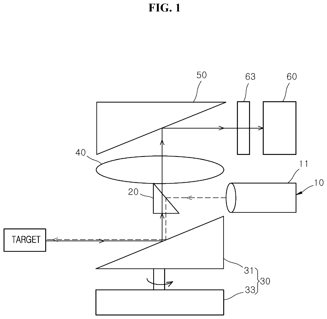
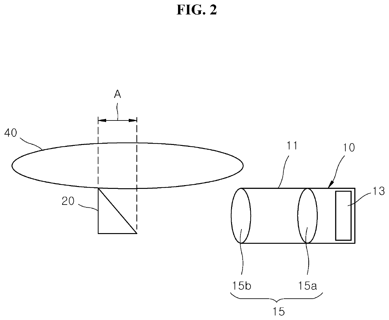
[0040]FIG. 1 is a diagram illustrating the configuration of the LiDAR sensing device in accordance with the first embodiment of the present invention, and FIG. 2 is a diagram illustrating the configuration of a sensing light source unit, a light receiving lens and a light receiving reflector in the LiDAR sensing device in accordance with the first embodiment of the present invention.

[0041]Referring to FIGS. 1 and 2, the LiDAR sensing device in accordance with the first embodiment of the present invention includes a sensing light source unit 10, a light transmitting reflector 20, a scanner unit 30, a light receiving lens 40, a light receiving reflector 50 and an optical detecting unit 60.

[0042]The sensing light source unit 10 radiates sensing light. The sensing light source unit 10 is disposed to deviate from the optical path of the light receiving lens 40 and the light receiving reflector ...

second embodiment

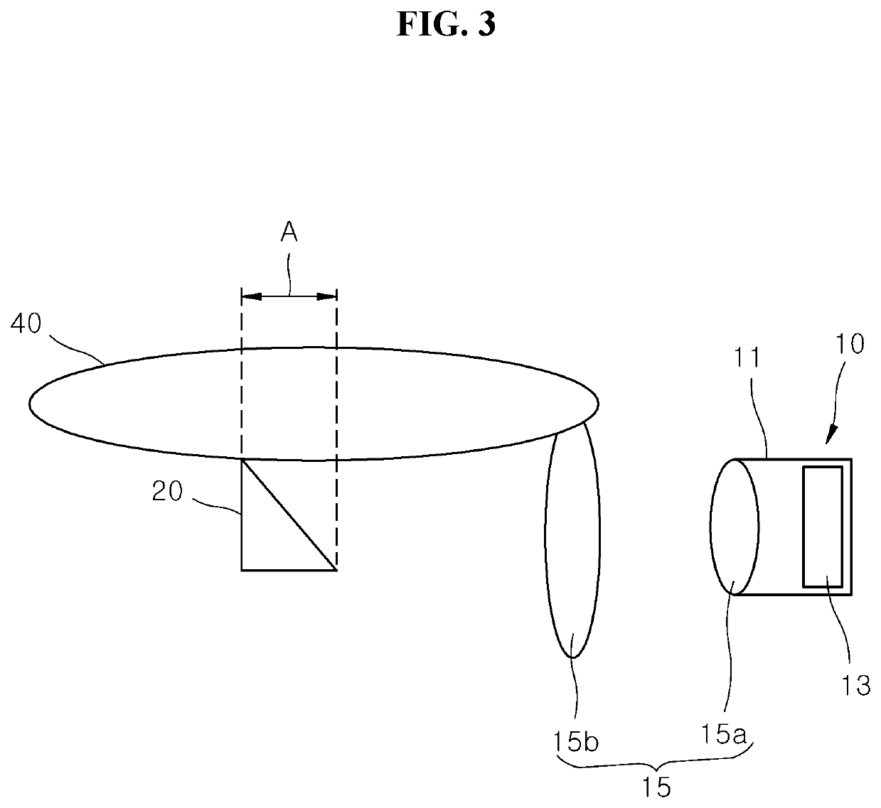
[0059]FIG. 3 is a diagram illustrating the configuration of a sensing light source unit, a light receiving lens and a light receiving reflector in the LiDAR sensing device in accordance with the present invention.

[0060]Referring to FIG. 3, the sensing light source unit 10 in accordance with the second embodiment of the present invention includes a barrel 11, a light source 13 and a light transmitting lens unit 15.

[0061]The barrel 11 is disposed to deviate from the optical path of the light receiving lens 40. The barrel 11 may be formed in a cylindrical shape. The light source 13 is installed in the barrel 11. The light transmitting lens unit 15 is provided on an output side of the light source 13 to collimate the sensing light radiated from the light source 13. Since the light transmitting lens unit 15 collimates the sensing light into parallel rays, the output of the sensing light can be improved.

[0062]The light transmitting lens unit 15 includes a first light transmitting lens 15a...

third embodiment

[0065]Next, a LiDAR sensing device in accordance with the present invention will be described.

[0066]FIG. 4 is a diagram illustrating the configuration of the LiDAR sensing device in accordance with the third embodiment of the present invention, and FIG. 5 is a diagram illustrating the configuration of a sensing light source unit, a light receiving lens and a light receiving reflector in the LiDAR sensing device in accordance with the third embodiment of the present invention.

[0067]Referring to FIGS. 4 and 5, the LiDAR sensing device in accordance with the third embodiment of the present invention includes a sensing light source unit 10, a scanner unit 30, a light receiving lens 40, a light receiving reflector 50 and an optical detecting unit 60.

[0068]The sensing light source unit 10 radiates sensing light. The sensing light source unit 10 is disposed in the optical path of the light receiving lens 40 and the light receiving reflector 50. Thus, since the sensing light source unit 10 ...


PUM


Abstract

A LiDAR sensing device may include: a sensing light source unit configured to radiate sensing light; a light transmitting reflector configured to reflect the sensing light radiated from the sensing light source unit; a scanner unit configured to reflect the sensing light reflected from the light transmitting reflector into a target, and to reflect incident light reflected from the target; a light receiving lens configured to pass the incident light reflected from the scanner unit, and integrated with the light transmitting reflector; a light receiving reflector configured to reflect the incident light passing through the light receiving lens; and an optical detecting unit into which the incident light reflected from the light receiving reflector is incident.

Description

CROSS-REFERENCES TO RELATED APPLICATION[0001]This application claims priority from and the benefit of Korean Patent Application No. 10-2018-0076440, filed on Jul. 2, 2018, which is hereby incorporated by reference for all purposes as if fully set forth herein.BACKGROUNDField[0002]Exemplary embodiments relate to a LiDAR (Light Detection and Ranging) sensing device, and more particularly, to a LiDAR sensing device, which reduces a blockage area, thus improving light receiving efficiency and decreasing the number of components.DISCUSSION OF THE BACKGROUND[0003]As the technology of vehicles is developed, functions including autonomous driving as well as autonomous parking are required. In order to perform these functions, a need for a LiDAR sensor is increasing.[0004]The LiDAR sensor is mounted on a bumper of a vehicle to detect the front and rear of the vehicle and thus detect an object, a structure or the like. The LiDAR sensor is installed in glass or a structure of a vehicle body. T...

Claims


Application Information

Patent Timeline
Patent Type & Authority Applications(United States)
IPC IPC(8): G01S7/481G01S17/08
CPCG01S7/4817G01S17/08G01S7/4813G01S7/4814G01S17/931G01S7/4816G01S17/42G01S7/4812G05D1/024
Inventor KIM, WON GYUMKIM, YOUNG SHINKIM, KYUNG RINJO, SUNG EUN
Owner HYUNDAI MOBIS CO LTD
Why Eureka
Try Eureka