Vehicle wheel

Active Publication Date: 2020-01-09
HONDA MOTOR CO LTD
View PDF5 Cites 2 Cited by
  • Summary
  • Abstract
  • Description
  • Claims
  • Application Information

AI Technical Summary

Benefits of technology

[0004]However, the conventional wheel (e.g., see Japanese Patent No. 4551422) has a problem in that the size of the main body portion in the wheel width direction is limited by the extending edge portions. This causes a further problem in that the conventional wheel cannot secure a large volume of the

Problems solved by technology

However, the conventional wheel (e.g., see Japanese Patent No. 4551422) has a problem in that the size of the main body portion in the wheel width direction is limited by t

Method used


Image

  • Vehicle wheel
  • Vehicle wheel
  • Vehicle wheel

Examples


Example

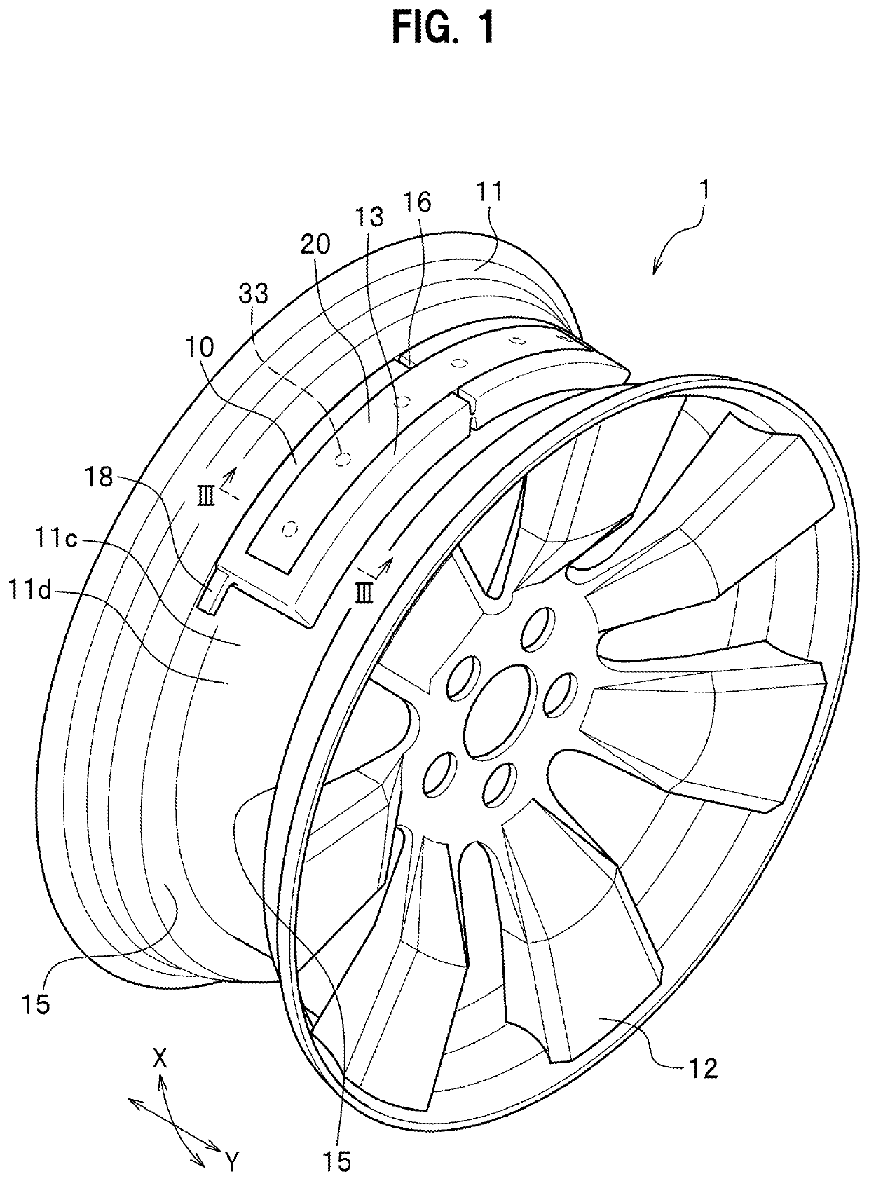
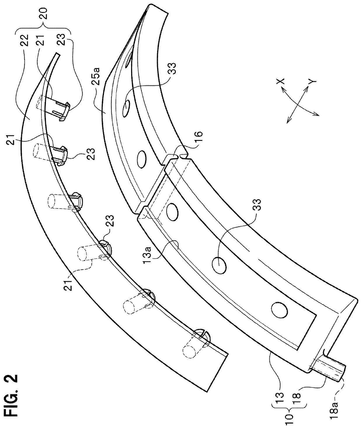
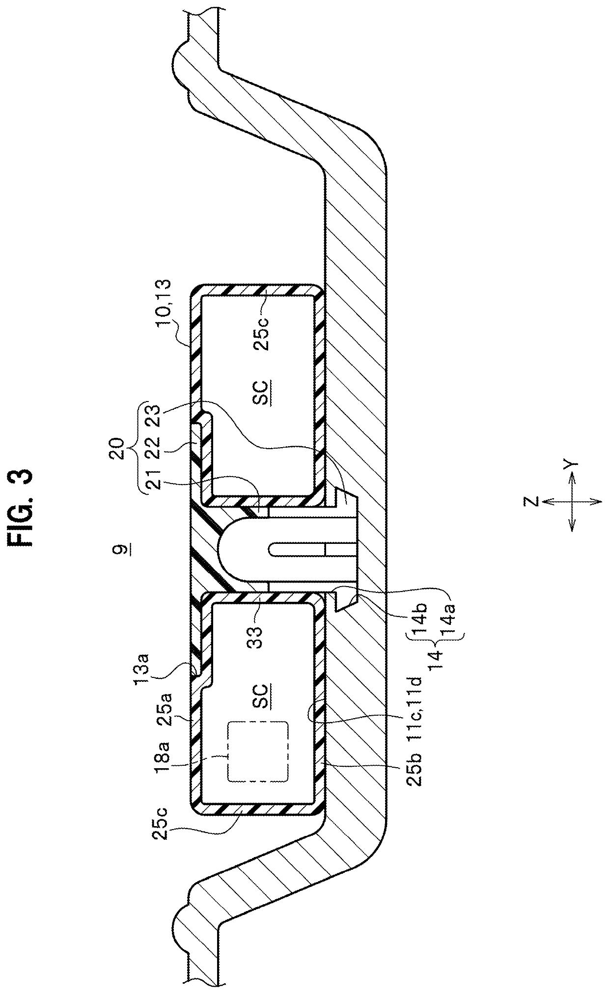
[0019]Next, a vehicle wheel according to an embodiment of the present invention is described in detail with reference to the drawings as needed. In the referenced drawings, “X” indicates a wheel circumferential direction, “Y” indicates a wheel width direction, and “Z” indicates a wheel radial direction.

[0020]Hereinafter, a description will be given of an overall configuration of the vehicle wheel. Next, a description will be given of a sub-air chamber member (Helmholtz resonator) and a joining member for attaching the sub-air chamber member to the well portion.

Overall Configuration of Vehicle Wheel

[0021]FIG. 1 is a perspective view of a vehicle wheel 1 according to an embodiment of the present invention.

[0022]As shown in FIG. 1, the vehicle wheel 1 according to the present embodiment has a rim 11 and a sub-air chamber member 10 (Helmholtz resonator) attached to the rim 11. The rim 11 is made of a metal such as an aluminum alloy or a magnesium alloy. The sub-air chamber member (Helmh...


PUM


Abstract

A vehicle wheel includes: a rim including a well portion with an outer circumferential surface, the well portion having a recessed portion formed on the outer circumferential surface; a sub-air chamber member serving as a Helmholtz resonator; and a joining member including a joining portion disposed in the recessed portion. The sub-air chamber member is attached to the outer circumferential surface of the well portion via the joining member.

Description

CROSS-REFERENCE TO RELATED APPLICATIONS[0001]The present application claims priority under 35 U.S.C. § 119 to Japanese Patent Application No. 2018-129704, filed Jul. 9, 2018, the contents of which are hereby incorporated by reference in their entirety.BACKGROUND OF THE INVENTION1. Field of the Invention[0002]The present invention relates to a vehicle wheel.2. Description of the Related Art[0003]There has been known a wheel including a well portion with an outer circumferential surface and a Helmholtz resonator (sub-air chamber member) that is attached to the outer circumferential surface and cancels air column resonance noises in a tire air chamber (e.g., see Japanese Patent No. 4551422). The sub-air chamber member of the wheel includes a main body portion formed elongated in a wheel circumferential direction and defining a sub-air chamber inside the main body, and a pair of plate-shaped edge portions that are formed on wheel width direction two ends of the main body along a substan...

Claims


Application Information

Patent Timeline
IPC IPC(8): B60R13/08B60B21/12G10K11/172
CPCB60R13/0884B60B21/12B60B2900/133G10K11/172B60B27/0047
Inventor KAMIYAMA, YOUICHISAITO, TOSHINOBUOSAWA, YUSUKE
Owner HONDA MOTOR CO LTD
Why Eureka
Try Eureka