Latency reduction in touch sensitive systems

a technology of touch-sensitive systems and latency reduction, applied in the field of touch-sensitive devices, can solve problems such as degrading user experience and variable latency, and achieve the effect of reducing latency and reducing latency

Active Publication Date: 2020-01-09
BEECHROCK LTD
View PDF1 Cites 15 Cited by
  • Summary
  • Abstract
  • Description
  • Claims
  • Application Information

AI Technical Summary

Benefits of technology

[0004]A touch sensitive system includes a touch surface, a display, and a latency control system. The latency control system reduces the latency between a touch event occurring on the touch surface and a graphical response displayed by the display. Specifically, the latency control system is a feedback system that synchronizes touch scan and display operations. The touch scan and display operations are synchronized by adjusting timing parameters, such as the start times and frequencies of the scan and display operations. Thus, the latency control system is an adaptable system that may reduce latency even when the processing times of various operations vary over time.

Problems solved by technology

This can result in noticeable variations in latency and degrade user experience.

Method used


Image

  • Latency reduction in touch sensitive systems
  • Latency reduction in touch sensitive systems
  • Latency reduction in touch sensitive systems

Examples


Embodiment Construction

I. Introduction

[0033]A. Device Overview

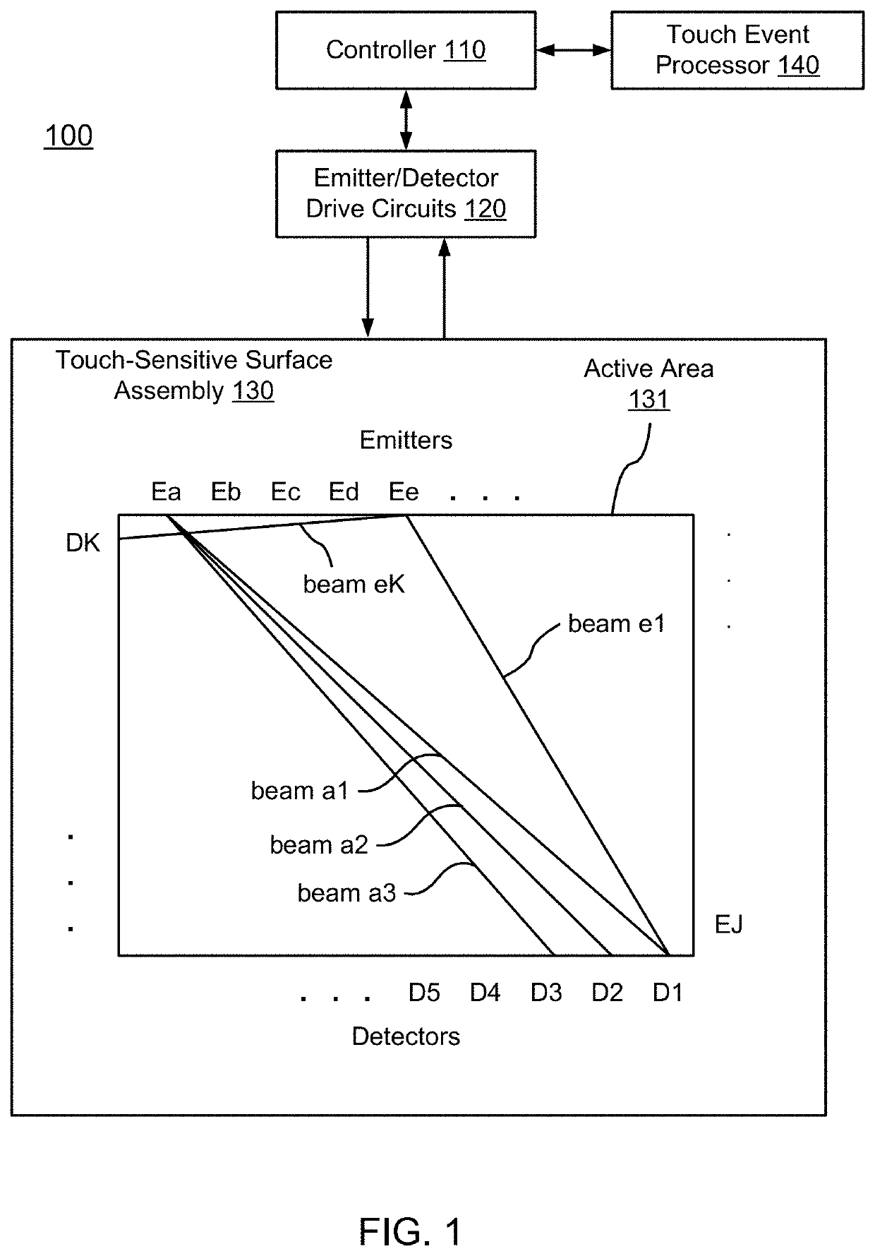
[0034]FIG. 1 is a diagram of an optical touch sensitive device 100, according to one embodiment. The optical touch sensitive device 100 includes a controller 110, emitter / detector drive circuits 120, and a touch sensitive surface assembly 130. The surface assembly 130 includes a surface 131 over which touch events are to be detected. For convenience, the area defined by surface 131 may sometimes be referred to as the active touch area or active touch surface, even though the surface itself may be an entirely passive structure. The assembly 130 also includes emitters and detectors arranged along the periphery of the active touch surface 131 (although the emitters and detectors may only be arranged along a portion of the periphery). In this example, there are J emitters labeled as Ea-EJ and K detectors labeled as D1-DK. The device also includes a touch event processor 140, which may be implemented as part of the controller 110 or separately as sh...


PUM


Abstract

A touch sensitive system includes a touch surface, a display, and a latency control system. The latency control system reduces the latency between a touch event occurring on the touch surface and a graphical response displayed by the display. Specifically, the latency control system is a feedback system that synchronizes touch scan and display operations. The touch scan and display operations are synchronized by adjusting timing parameters, such as the start times and frequencies of the scan and display operations. Thus, the latency control system is an adaptable system that may reduce latency even when the processing times of various operations vary over time.

Description

CROSS REFERENCE TO RELATED APPLICATIONS[0001]This application claims the benefit of priority to U.S. Provisional Patent Application No. 62 / 694,640, “Latency Reduction in Touch-Sensitive Systems,” filed on Jul. 6, 2018, which is incorporated by reference.BACKGROUND1. Field of Art[0002]This description generally relates to a touch sensitive device, and specifically to reducing latency between a touch event on the device and displaying an image indicative of the touch event.2. Description of the Related Art[0003]Touch sensitive displays for interacting with computing devices are becoming more common. A number of different technologies exist for implementing touch sensitive displays and other touch sensitive devices. Examples of these techniques include, for example, resistive touch screens, surface acoustic wave touch screens, capacitive touch screens, and certain types of optical touch screens. Reducing the latency between a user interacting with a touch surface and a display displayi...

Claims


Application Information

Patent Timeline
Patent Type & Authority Applications(United States)
IPC IPC(8): G06F3/041G06F3/042
CPCG06F3/0421G06F3/04166G06F3/0428
Inventor DRUMM, OWENPHELAN, CATHAL G.
Owner BEECHROCK LTD
Why Eureka
Try Eureka