
Apparatus for collecting samples of drill cuttings and method of use

a drill cutting and apparatus technology, applied in the field of automatic process of collecting drill cuttings, can solve the problems that the throughput and functionality of these measurements may not be adequate to support the drilling process, and none of the prior art above addresses the practical aspects of drill cutting sampling and preparation needed to enable quantitative high throughput measurements

Inactive Publication Date: 2020-01-16
STEPANOV VITAL +2
View PDF0 Cites 5 Cited by
  • Summary
  • Abstract
  • Description
  • Claims
  • Application Information

AI Technical Summary

Benefits of technology

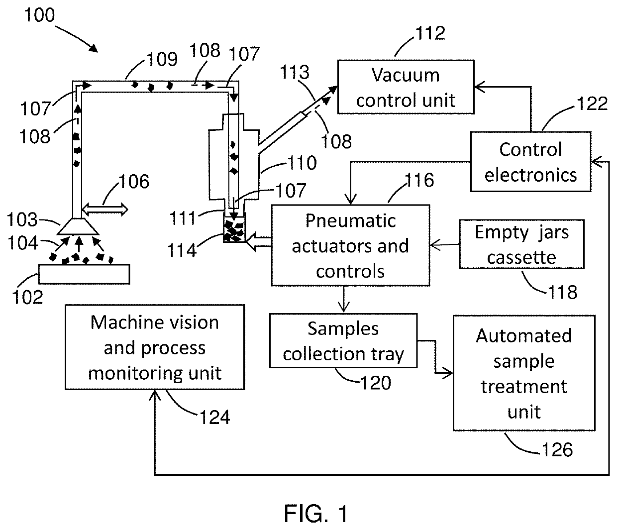
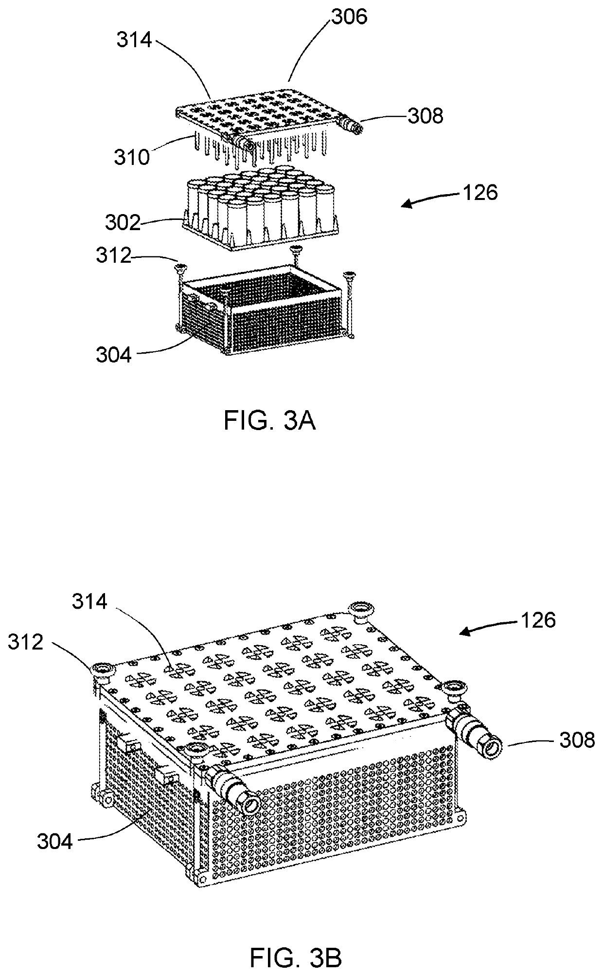
The present invention relates to an apparatus and method for collecting samples of drill cuttings using vacuum assisted cuttings transfer from a shale shaker to a sample jar. The apparatus includes a movable inlet port, a suction line to transfer cuttings from the inlet port to a discharge chamber, adjustable to control surface moisture of the drill cuttings. It also includes pneumatic actuators to control position of the inlet port and sample jar, an electronics unit placed in an explosion-proof enclosure. The apparatus may also include a vacuum control unit and a jar cassette for empty jars and samples collection tray. The apparatus may also include a machine vision device to monitoring the amount of drill cuttings at the movable inlet or providing the cuttings sample description. The apparatus may also include an automated sample treatment unit for simultaneous treatment of a plurality of drill cuttings samples in the sample jars, including at least one of (i) automated washing, (ii) automated drying, or (iii) filling space between the cuttings fragments in the jar with a fluid having known properties. This leads to a method for surface logging using measurements on drill cuttings collected and treated automatically, including formations evaluation using bulk-sensitive measurements such as natural gamma spectroscopy and nuclear magnetic resonance relaxometry.

Problems solved by technology

These measurements are typically performed in laboratory, the throughput and functionality of these measurements may not be adequate to support the drilling process.
None of the prior art above address practical aspects of the drill cuttings sampling and preparation needed to enable quantitative high throughput measurements.

Method used


Image

  • Apparatus for collecting samples of drill cuttings and method of use
  • Apparatus for collecting samples of drill cuttings and method of use
  • Apparatus for collecting samples of drill cuttings and method of use

Examples


Embodiment Construction

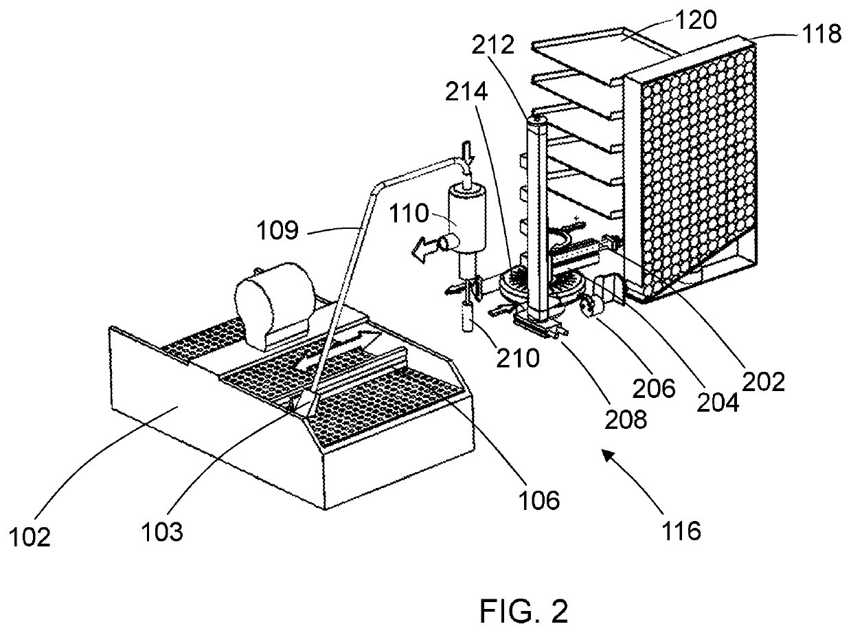
[0014]FIG. 1 illustrates a conceptual view of the apparatus of the present invention. The apparatus comprises a cuttings transfer unit 100 including a cuttings inlet port 103 to acquire cuttings from the surface of a shaker 102 or, alternatively, from a cuttings receiving board (the cuttings entering the inlet port are shown at 104), a cuttings inlet port displacement actuator 106 to scan the surface of the shake during the cuttings acquisition from the shaker surface, and an adjustable suction line 109 (flexible, with adjustable length) to transfer cuttings from the inlet port to the discharge chamber 110. The adjustable suction line is also used to substantially eliminate (or reduce as needed) moisture on the surface of the cuttings fragments. The moisture is reduced during transferring cutting in the suction line. The length of the line controls the level of the moisture reduction. The moisture control is required for some measurements on drill cutting, for example, for nuclear ...


PUM


Abstract

An apparatus and a method for surface logging include a vacuum assisted transfer of drill cuttings from a shale shaker to sample jars. The cuttings samples are used for measurements to characterize formations in which a wellbore is drilled. The apparatus has an adjustable suction line that can be used to control moisture on the surface of the drill cuttings fragments. The method includes an automated sample collection and a high throughput sample treatment (e.g., washing or / and a controllable drying) to increase value of measurements.

Description

CROSS-REFERENCE TO RELATED APPLICATIONS[0001]This application is related to a provisional patent application claiming the benefit 35 USC 119(e). The provisional patent application number is U.S. Pat. No. 62 / 696,821; filing date is Jul. 11, 2018.BACKGROUND OF THE INVENTIONField of the Invention[0002]This invention is related to an automated process of collecting drill cuttings at a shale shaker during the drilling operation. More specifically, the invention teaches apparatus and methods for fast automated sampling and preparation of the drill cuttings to enable continuous evaluation of petrophysical properties (e.g., properties evaluated based on natural gamma spectroscopy and nuclear magnetic resonance relaxometry) of the earth formations while drilling an oil well.Background Art[0003]Cost efficient drilling operation would greatly benefit from lower cost and high throughput quantitative data acquisition to evaluate the rock formations being drilled. Advanced mud logging including m...

Claims


Application Information

Patent Timeline
IPC IPC(8): E21B49/02E21B21/06E21B21/01
CPCE21B21/01E21B49/02E21B49/005B65G53/24E21B21/066E21B21/06G01N1/00
Inventor STEPANOV, VITALYREIDERMAN, ARCADYKRUGLIAK, ZINOVY B.
Owner STEPANOV VITAL
Learn More