
Micro-optical component for generating an image

a micro-optical component and image technology, applied in the field of micro-optical components for generating images, can solve the problems of single spherical lens suffering from spherical aberration, the largest loss of large field of view,

Inactive Publication Date: 2020-01-16
CSEM CENT SUISSE DELECTRONIQUE & DE MICROTECHNIQUE SA RECH & DEV
View PDF0 Cites 1 Cited by
  • Summary
  • Abstract
  • Description
  • Claims
  • Application Information

AI Technical Summary

Benefits of technology

The patent describes a device with a lens and a micro-optical component that has an obscuration element. The lens covers the aperture and the focal point is on the second surface. The obscuration element prevents some of the light beams from passing through the lens, resulting in a more uniform image and reduced blur.

Problems solved by technology

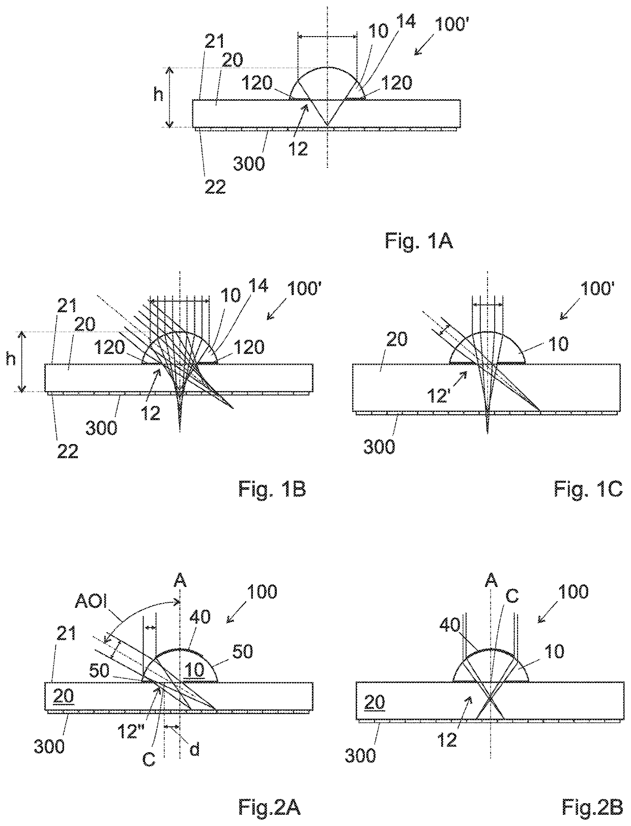
However, the known micro-optical component of FIG. 1A presents two main drawbacks, in particular for large field of views (with maximum viewing angles equal or higher than 100°, e.g. 120°): intensity fall-off at the image edge and spherical aberrations.
First, large field of views suffer most from the intensity fall-off at the image edge.
Secondly, for wide viewing angles a single spherical lens suffers from spherical aberrations, visible in FIG. 1B.

Method used


Image

  • Micro-optical component for generating an image
  • Micro-optical component for generating an image
  • Micro-optical component for generating an image

Examples


Embodiment Construction

[0047]FIG. 2A shows a cut-section view of one embodiment of a micro-optical component 100 according to the invention. As the known micro-optical component 100′ of FIGS. 1A to 1C, it comprises:[0048]a substrate 20, comprising a first surface 21 and a second surface 22, wherein the first surface comprises an aperture 12″, and the second surface is arranged to be connected to an image sensor comprising a pixel array 300, e.g. via a glue or adhesive layer (not illustrated),[0049]a lens 10, placed on the first surface 21 so as to cover aperture 12″, the focal point of the lens 10 belonging to the second surface 21.

[0050]The presence of a substrate 20 allows to avoid internal reflection in the lens 10, in particular for large AOIs.

[0051]In one preferred embodiment, the refractive index of the substrate 20 is substantially equal to the refractive index of the lens 10.

[0052]According to the invention, the micro-optical component 100 of FIG. 2A comprises an obscuration element. In the embodi...


PUM

PropertyMeasurementUnit
sizeaaaaaaaaaa
optic heightaaaaaaaaaa

Abstract

A micro-optical component for generating an image, including a substrate and a lens. The substrate, includes a first surface and a second surface, wherein the first surface includes an aperture, and the second surface is arranged to be connected to a pixel array. The lens is placed on the first surface so as to cover the aperture. The focal point of the lens belongs to the second surface. The lens includes an obscuration element generating at the lens an obscured area and an unobscured area. The obscuration element is dimensioned to reduce the light transmittance towards the pixels for a fraction of the viewing angles only and at the same time. The obscured area is dimensioned so that the optical resolution of the lines is not smaller than the image resolution given by the size of the pixels.

Description

REFERENCE DATA[0001]The present invention claims the priority of European Patent Application EP20180182654, filed on Jul. 10, 2018, the content of which is incorporated here by reference.FIELD OF THE INVENTION[0002]The present invention concerns a micro-optical component for generating an image. The present invention concerns also an imaging device comprising this micro-optical component, a method for manufacturing the micro-optical component and a method for manufacturing the imaging device.DESCRIPTION OF RELATED ART[0003]Nowadays, imaging devices, as for example and in a non-limiting way micro cameras, endoscopic cameras, light-weight vision systems for flying robots, and similar devices comprise image sensors connected, preferably directly connected, to ultra-thin or very flat optical components, so as to obtain an optic height in the order of few millimeters.[0004]In this context, the optic height is the height (or the thickness) of optical component from the surface of the opti...

Claims


Application Information

Patent Timeline
Patent Type & Authority Applications(United States)
IPC IPC(8): H04N5/225G02B27/09G02B3/00
CPCG02B3/0087G02B27/0955G02B2003/0093H04N5/2254G02B13/0085H01L27/14627B29D11/00307B29D11/00375H04N23/55
Inventor GIMKIEWICZ, CHRISTIANENUSSBAUM, PASCALHENDRICKS, NICHOLAS
Owner CSEM CENT SUISSE DELECTRONIQUE & DE MICROTECHNIQUE SA RECH & DEV
Learn More