Control system for a vehicle and method

Pending Publication Date: 2020-01-23
JAGUAR LAND ROVER LTD
View PDF0 Cites 3 Cited by
  • Summary
  • Abstract
  • Description
  • Claims
  • Application Information

AI Technical Summary

Benefits of technology

[0057]In one aspect of the invention for which protection is sought there is provided a motor vehicle having a control system that assists a driver driving a vehicle over rocky terrain by automatically controlling the application of a braking system of the vehicle to prevent (1) rollback if a driver releases an accelerator control such as an accelerator pedal whilst mounting a step-like obstacle such as a rock, and/or (2) forward lurch when the vehicle mounts the step-like obstacle. Thus, a driver is required substantially only to control an accelerator of the vehicle such as an accelerator pedal, and steer the vehicle in the case of a vehicle not configured automatically to steer. The feature of automatic brake control in this manner may be referred to as a ‘creep mode’, ‘single pedal crawl mode’ or other suitable title. The feature may be automatically triggered when one or more conditions are met, and/or selected automatically by a user when required. In the case of automatic triggering, in some embodiments the feature may be triggered in the event that the control system detects that the vehicle has stopped abruptly due to a wheel of the vehicle encountering an obstacle at low speed, in which case rollback of the vehicle may be substantially immediately countered by application of the braking system. For example, if the vehicle has stopped moving and the control system determines that the amount of powertrain torque being developed substantially at the moment the vehicle stops is sufficient to maintain progress over the terrain (by reference to the

Problems solved by technology

By way of example, it is to be understood that the Sand driving mode may not provide

Method used


Image

  • Control system for a vehicle and method
  • Control system for a vehicle and method
  • Control system for a vehicle and method

Examples


Example

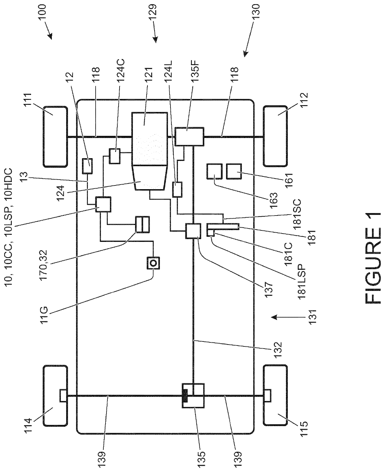
[0068]FIG. 1 shows a vehicle 100 according to an embodiment of the invention intended to be suitable for off-road use, that is for use on terrains other than regular tarmac road, as well as on-road. The vehicle 100 has a powertrain 129 that includes an engine 121 that is connected to a driveline 130 having an automatic transmission 124 controlled by a transmission controller 124C. The transmission 124 has a transmission mode selector dial 124L permitting a driver to select the required transmission operating mode selected from park (P), forward drive (D), neutral (N) and reverse drive (R).

[0069]The driveline 130 is arranged to drive a pair of front vehicle wheels 111,112 by means of a front differential 135F and a pair of front drive shafts 118. The driveline 130 also comprises an auxiliary driveline portion 131 arranged to drive a pair of rear wheels 114, 115 by means of an auxiliary driveshaft or prop-shaft 132, a rear differential 135 and a pair of rear driveshafts 139. It is to ...


PUM


Abstract

The invention provides a system (10) for a motor vehicle (100) that receives drive demand information (161S) indicative of an amount of drive demanded of a powertrain (129) of the vehicle (100), and controls an amount of drive torque applied by the powertrain (129) to one or more road wheels (111,112, 114, 115) in dependence on the drive demand information (116S). The system also receives gradient information (11GS) relating to the driving surface and vehicle speed information (Sv). The control system, in dependence on the gradient and speed information, automatically causes a braking system (12d) to apply brake force to one or more of the wheels (111, 112, 114, 115) to prevent vehicle rollback, and adjusts the amount of brake force applied in dependence on the drive demand information (161S) to cause the amount of brake force applied to increase progressively as the amount of drive demand decreases.

Description

INCORPORATION BY REFERENCE[0001]The content of co-pending UK patent applications GB2507622 and GB2499461 are hereby incorporated by reference. The content of U.S. Pat. No. 7,349,776 and co-pending international patent applications WO2013 / 124321 and WO2014 / 139875 are incorporated herein by reference. The content of UK patent applications GB2492748 and GB2499279 and UK patents GB2492655 and GB2508464 are also incorporated herein by reference.TECHNICAL FIELD[0002]The present disclosure relates to a vehicle controller and control method and particularly, but not exclusively, to a controller and a method for controlling operation of one or more vehicle systems or subsystems in a land-based vehicle capable of driving in a variety of different and extreme terrains and conditions. Aspects of the invention relate to a controller, to a control system, a vehicle, a method, a non-transitory computer readable carrier medium carrying a computer readable code, a computer program product executable...

Claims


Application Information

Patent Timeline
IPC IPC(8): B60W30/18B60W10/04B60W10/18
CPCB60W10/04B60W2710/18B60W30/18118B60W2710/083B60W2550/142B60W2710/0666B60W10/18B60W2520/10B60W10/182B60W30/18054B60T2201/06B60T2201/09B60W30/18072B60W30/18109B60W2540/10B60W2710/182B60W2552/15B60T7/12B60T8/24B60W30/18063
Inventor BURFORD, ROBERTCOOKE, CHARLOTTEARMSTRONG, DAVID
Owner JAGUAR LAND ROVER LTD
Why Eureka
Try Eureka